Mike and PMA,
These are good points, all. We should pay more attention to these issues of layout and wiring (and I don't mean the number of pure copper 9's after the decimal).
One issue to consider is the effect of the grounding point of the feedback divider. If you look at the effective input voltage at the input of the amplifier proper, in a high feedback design, it's often just a few mV: the difference between the applied Vin and the returned Vfeedback. If you connect the bottom of the feedback divider at an improper grounding point, where there is even a fraction of a mV of ripple or other junk, that small error signal appears almost unattenuated at the input proper of the amp, which happily amplifies it with its open loop gain. So, although this is not a feedback problem in itself, it certainly is related to it. One must hope that this is controlled in commercial products, and it certainly will immediately show up in distortion measurements; but it may be a reason why many DIY'ers can report conflicting experiences with high feedback designs.
Jan Didden
janneman said:One must hope that this is controlled in commercial products,
Jan,
unfortunately, it is not controlled in a majority of commercial products. Highly qualified and experienced DIYer can obtain better result in this field than some 95% of available commercial products.
Regards,
Pavel
Re: Re: Re: Re: Re: Re: BJT distortion vs emitter degeneration
Klaus,
You make a very good point in response to the question “why bother with Class A?’ The fact that in Class A the output stage supply currents are essentially a linear representation of the signal, rather than half-wave rectified versions, is very helpful in eliminating a large source of nonlinear, correlated trash currents in the amplifier. These non-linear currents can couple magnetically into the signal path and also via ground paths, power supply rails, etc.
However, any such coupling of these horrid signals into the signal path will be readily apparent as distortion spectra in the output of the amplifier. I have personally experienced the difficulty of getting distortion numbers down in light of these kinds of disturbances.
This is one of the reasons why I strive for designs with extremely small amounts of distortion. Such an amplifier will unmask distortions that are symptomatic of things like leakage of Class-AB half-wave rectified signals into the signal path. Put another way, an amplifier with less than 0.001% THD-20 leaves very little room for these potentially bad-sounding distortions to be present.
Suppose one has a Class-A amplifier and a Class-AB amplifier, both with a respectable 0.01% THD-20. The Class A amplifier may have relatively benign distortions mostly of second and third order making up the 0.01%, while the Class-AB amplifier may have malevolent crossover and nonlinear power supply originated distortions making up most of its 0.01% THD. They may sound different even though they measure the same with a conventional single-number measurement.
Finally, suppose we knew that we could not perceive any distortion below 0.001%, no matter what its composition or order (we don’t know that, of course). Now suppose we have a Class-A amplifier and a Class-AB amplifier that both have less than 0.001% distortion. Under these conditions, do we have a good reason to pick the much more expensive Class-A amplifier? Does the Class-A amplifier still sound better, even if they are built with the same high quality components and attention to detail? If so, why? This might be one of the mysteries.
Cheers,
Bob
KSTR said:Besides "absence" of low level signal output stage distortion the most prominent characteristic of class-A is that there not much uncorrelated signal flying around, that is, no rectified load currents in the PSU lines. And in a constant current class-A bridge the PSU completely is out of the picture, WRT load currents. That makes class-A more tolerant to layout/wiring compromises, it seems...
Klaus
Klaus,
You make a very good point in response to the question “why bother with Class A?’ The fact that in Class A the output stage supply currents are essentially a linear representation of the signal, rather than half-wave rectified versions, is very helpful in eliminating a large source of nonlinear, correlated trash currents in the amplifier. These non-linear currents can couple magnetically into the signal path and also via ground paths, power supply rails, etc.
However, any such coupling of these horrid signals into the signal path will be readily apparent as distortion spectra in the output of the amplifier. I have personally experienced the difficulty of getting distortion numbers down in light of these kinds of disturbances.
This is one of the reasons why I strive for designs with extremely small amounts of distortion. Such an amplifier will unmask distortions that are symptomatic of things like leakage of Class-AB half-wave rectified signals into the signal path. Put another way, an amplifier with less than 0.001% THD-20 leaves very little room for these potentially bad-sounding distortions to be present.
Suppose one has a Class-A amplifier and a Class-AB amplifier, both with a respectable 0.01% THD-20. The Class A amplifier may have relatively benign distortions mostly of second and third order making up the 0.01%, while the Class-AB amplifier may have malevolent crossover and nonlinear power supply originated distortions making up most of its 0.01% THD. They may sound different even though they measure the same with a conventional single-number measurement.
Finally, suppose we knew that we could not perceive any distortion below 0.001%, no matter what its composition or order (we don’t know that, of course). Now suppose we have a Class-A amplifier and a Class-AB amplifier that both have less than 0.001% distortion. Under these conditions, do we have a good reason to pick the much more expensive Class-A amplifier? Does the Class-A amplifier still sound better, even if they are built with the same high quality components and attention to detail? If so, why? This might be one of the mysteries.
Cheers,
Bob
MikeBettinger said:
My point is, one can design a circuit with vanishing low levels of distortion and still have cloudly/congested mess if the various stages have unintended noise or interference from the other stages circulating through them.
Regards, Mike.
Hi Mike,
I'm not surprized that your DIY version of the amplifier may have sounded better. I agree completely that the Devil can be in the details and the layout, etc.
However, I don't think this anecdote supports what you subsequently said above. First, It's doubtful that the H-K had vanishingly low distortion. Second, I strongly believe that unintended noise/interference that can corrupt the sound will necessarily show up in a measurement at the output of the amplifier, either as distortion spectra or as noise. So if I have an amplifier with vanishingly low distortion (say, less than 0.001%) and vanishingly low noise (say down 100 dB or more), where is the wiggle room for the hypothesis that you are putting forth?
What am I missing here? Please be patient with me; I am not trying to be agumentative. Rigorous testing of hypotheses, where possible, is how we all learn. Have any of us rigorously tested this hypothesis?
Cheers,
Bob
Bob Cordell said:Second, I strongly believe that unintended noise/interference that can corrupt the sound will necessarily show up in a measurement at the output of the amplifier, either as distortion spectra or as noise.
Not necessarily, as it is strongly whole-system dependent. I have measured examples of vanishingly low distortion amplifiers that failed with CD player with SMPS. Just for the reason of input and wiring topology.
Bob Cordell said:Hi Mike,
However, I don't think this anecdote supports what you subsequently said above. First, It's doubtful that the H-K had vanishingly low distortion.
Hi Bob,
The anecdote was basically background as to my focus over the years. Instead of focusing on circuit refinements etc., as the majority of the contributers to this discussion have displayed a proficiency for, I focused more on the execution of the equipment I've been exposed to, hence my different slant.
Not necessarily, as it is strongly whole-system dependent. I have measured examples of vanishingly low distortion amplifiers that failed with CD player with SMPS. Just for the reason of input and wiring topology.
Exactly my point.
Regards, Mike.
PMA said:
Not necessarily, as it is strongly whole-system dependent. I have measured examples of vanishingly low distortion amplifiers that failed with CD player with SMPS. Just for the reason of input and wiring topology.
Are you talking about a CD (or SACD) player that has poor output filtering and puts out too much ultrasonic content into the power amplifier?
If so, I agree with you on this, although one might argue about where the finger of blame should be pointed. In what way did the amplifier fail? One might ask what the amplitude and frequency of the garbage from the CD player was, and whether it made it to the output of the amplifier, and whether it popped a tweeter.
If the amplifier was a good design with plenty of slew rate (say, more than 50V/us), why was it so bothered by some garbage from a CD player?
If the amplifier was capable of full power at 20 kHz with, say 0.001% (vanishingly low, your words), it should be capable of being un-bothered by ultrasonic input signals at much lower levels. I think you need to be more specific here.
Also, If the CD player is putting out a very high level of supersonic energy, it is a piece of junk and does not belong in the system.
I have seen SACD players that put out some supersonic stuff, but not at really high levels.
Maybe we need a supersonic CCIF IM test for amplifiers where we drive them to 1/10 power with 99 kHz + 100 kHz.
Cheers,
Bob
MikeBettinger said:
Hi Bob,
The anecdote was basically background as to my focus over the years. Instead of focusing on circuit refinements etc., as the majority of the contributers to this discussion have displayed a proficiency for, I focused more on the execution of the equipment I've been exposed to, hence my different slant.
But both of these measurements are performed on a bench with shorted inputs or generated signals. Placed in someone system there would be no way to separate the noise being impressed on the signal in an interconnect cable caused by high frequency noise circulating between two components (preamp/CD player for example) based on their different ground potentials, or possibly noise picked up on the interconnect shields not properly terminated to the circuit ground. This noise voltage, depending on the routing of the ground reference, can be superimposed on the signal ground reference or supplies. My comments assume the design already possesses low noise and low distortion. This is tough to distill down to a couple of paragraphs.
I don't know what would be considered rigorous testing in this case. I got interested in audio by the time I was 10 and remember clearly listening to music and feeling that the music I loved was being interfered with by various things. I try to understand these interactions for my own listening pleasure and anything that adds or subtracts from my music is readily noted. I'm not aware of any way to put these observations and their physical implementations under the microscope, short of going into business, entering a well established playing field and being eaten alive based on everything but the performance. Audio has never had any forum of this sort.
Hopefully I've answered your questions, if not fire some more... 🙂
Regards, Mike.
Thanks for your thoughtful and patient response, Mike. These are all good points. And I do agree that execution is very important. A poor quality execution can ruin the best of designs. And a design that tests well on the bench in a limited battery of tests can be impaired by the system environment in which it is placed. No question about that.
I just think that we can do more than just speculate. Maybe that means tougher bench tets. Maybe that means measuring things like noise in-situ in the system environment where the amplifier is operating. I think if we work at it, we stand a good chance of getting that cat into the corner. I just don't place as much value on technical speculation and hypotheses that are not backed up by some evidence. We can do more, and that includes me.
Cheers,
Bob
janneman said:
One issue to consider is the effect of the grounding point of the feedback divider. If you look at the effective input voltage at the input of the amplifier proper, in a high feedback design, it's often just a few mV: the difference between the applied Vin and the returned Vfeedback. If you connect the bottom of the feedback divider at an improper grounding point, where there is even a fraction of a mV of ripple or other junk, that small error signal appears almost unattenuated at the input proper of the amp, which happily amplifies it with its open loop gain. So, although this is not a feedback problem in itself, it certainly is related to it. One must hope that this is controlled in commercial products, and it certainly will immediately show up in distortion measurements; but it may be a reason why many DIY'ers can report conflicting experiences with high feedback designs.
Jan makes a very important point here, not least so because it is often neglected/overlooked. It is common knowledge that any distortion arising in the mixing of NFB and original signal does not get cancelled by NFB - often the reverse in high NFB designs. But more than one classy design looses it exactly here even if only because component tolerances are neglected, not to mention the unbalance in the ubiquitous differential input configurations one way or another.
This is a fast-moving thread and I hope not to repeat when I mention that I am also somewhat surprised that thd is still mentioned as a yardstick - the dangerous effect of hidden high order products being present has been pointed out. I would hazard to say that at least some of the "undefinable/unmeasurable" effects mentioned recently are to be found here, allied to the basic problem that Jan has posted above. Again it might make sense to include sharp cut-off audio band end filters just before the power amplifier input, to get rid of what might come in from earlier "loose bolts". Anything is possible these days. One has read at least some reports where that cleaned up undefinable listener dissatisfaction. (Not to promote the "eat what you like then suck a [brand of antacid]" type of design practice.)
Bob Cordell said:
I just think that we can do more than just speculate. Maybe that means tougher bench tests. Maybe that means measuring things like noise in-situ in the system environment where the amplifier is operating. I think if we work at it, we stand a good chance of getting that cat into the corner. I just don't place as much value on technical speculation and hypotheses that are not backed up by some evidence. We can do more, and that includes me.
Cheers,
Bob
Hi Bob,
The first step is to speculate and the second is to determine what or how the thoughts can be tested. Computers and software have evolved to an interesting level where simultaneous parallel snapshots can be stored, normalized and compared, with the differences analysed in many ways.
As part of my real job I'm learning a program called LabView that allows the creation of virtual instruments that I see (innocently) as having endless possibilities in this regard. I'm about 8 months into it and the learning curve has been steep but over the next year I have two separate projects that require processing both optical and vibration spectrums that should, hopefully, educate me as to what is possible.
If you get a chance check it out. Facinating stuff.
Regards, Mike.
Johan Potgieter said:
Jan makes a very important point here, not least so because it is often neglected/overlooked. It is common knowledge that any distortion arising in the mixing of NFB and original signal does not get cancelled by NFB - often the reverse in high NFB designs.
Again it might make sense to include sharp cut-off audio band end filters just before the power amplifier input, to get rid of what might come in from earlier "loose bolts". Anything is possible these days. One has read at least some reports where that cleaned up undefinable listener dissatisfaction. (Not to promote the "eat what you like then suck a [brand of antacid]" type of design practice.)
Jan's comment's point to very real concerns and your comment on keeping the noise out right at the input parallels them. The biggest trick to making it work is making sure ground is doing what it should, which is harder than it looks. I'm building a MC phono preamp right now that is beating me up in this respect, just due to the amount of gain involved.
Regards, Mike.
Johan Potgieter said:
This is a fast-moving thread and I hope not to repeat when I mention that I am also somewhat surprised that thd is still mentioned as a yardstick - the dangerous effect of hidden high order products being present has been pointed out. I would hazard to say that at least some of the "undefinable/unmeasurable" effects mentioned recently are to be found here, allied to the basic problem that Jan has posted above. Again it might make sense to include sharp cut-off audio band end filters just before the power amplifier input, to get rid of what might come in from earlier "loose bolts".
Bear in mind that while THD is mentioned often, as it is a convenient yardstick, I and many others are always ultimately depending on the spectrum of the THD distortion product, not just the single number. There is also a large amount of importance placed of full spectral analysis of the CCIF 19 kHz + 20 kHz IM distortions.
Single-number THD specs, especially at 1 kHz, have been abused and abused, and have given THD a bad rap. But don't throw out the baby with the bathwater. Properly interpreted in a spectral context, THD and CCIF IM tell us a great deal about linearity.
One problematic limitation of THD is that we often care most about HF THD, like THD-20. Yet far too many THD-20 measurements are made only in an 80 kHz bandwidth. This seriously attenuates many of the higher-order components that we care about. My THD analyzer goes out to 200 kHz, which is more realistic, but few reviews are seen with this amount of bandwidth. Indeed, sometimes you will see THD vs frequency plots where the THD appears to get better above 15 kHz or so. That is usually a dead giveaway that upper harmonics are being attenuated by the 80 kHz filter in the analyzer. Analyzer manufacturers like that 80 kHz filter because it allows them to quote a lower distortion residual, partly due to the lower resulting measurement noise bandwidth.
Bottom line is that, apart from a simulation world, 19 + 20 kHz CCIF IM spectral analysis is much more reliable for spotting high order nonlinearity at high frequencies, since the nonlinearities are folded in-band.
Note also that if there are nonlinear power supply current gyrations in the Class-AB output stage that make their way back to the input summing node by, for example, poor grounding topology, they will very definitely be present in the THD and CCIF IM spectra.
You are absolutely correct that some amount of LFP filtering at the input of power amplifiers is desirable.
Cheers,
Bob
EMI Ingress
Although we have departed a bit from the topic of negative feedback per se, we have been touching on that important topic of EMI ingress. This can be an issue for amplifiers whether they use NFB or not.
While I like to ask the tough, sometimes Devil's advocate questions regarding this topic (and others), I take the issue of EMI ingress in power amplifiers very seriously. Indeed, I am guilty of perhaps over-designing in this area without hard evidence of the need. I assume that there is bad stuff out there and that it can affect the sound, and design accordingly. I would still like to ask the tough questions and understand the EMI environment better, including its cause and effect in regard to how it affects sonics. For example, If EMI is getting in and messing with the circuits enough to impair the sonics, why can’t we hear artifacts of the EMI in the loudspeaker?
As Mike said, we start with hypotheses, then we test them. Sometimes testing them is where we all could do a better job.
As we know, there are at least three external-world ports where EMI ingress can happen in a power amplifier. These are the input, the output and the mains. In addition, there are internal opportunities as from rectifier switching, imperfect grounding topology and Class-AB output stage signal-rectified currents.
Here are some of the things I do in my amplifiers as defenses against EMI. I know that many of you do many of these as well. I also agree that some commercial amplifiers, including some high-end ones, probably don’t do enough.
1) I use two stages of gentle R-C roll-off in front of the input stage. Even though the internal amplifier may have a closed loop bandwidth exceeding 1 MHz, I limit the overall pass-band to about 250 kHz.
2) I use a quasi-differential input arrangement that breaks ground loops and provides some common mode rejection.
3) I use JFET input stages that tend to have high input voltage dynamic range and that do not present the input with a semiconductor junction where rectification may take place.
4) I never use a lead compensation capacitor across the feedback resistor; such a capacitor greatly increases the coupling of garbage at the output terminals back to the input stage.
5) I design the amplifiers with at least 100 V/us slew rate, so that if any high frequency stuff gets in, it will likely be treated linearly.
6) I design the amplifier-proper to have very high natural PSRR out to fairly high frequencies. This includes trying to use feedback compensation that does not degrade HF PSRR.
7) I use an output coil, albeit usually only 0.5 uH in parallel with 0.5 ohms.
8) I place R-C Zobel networks on both sides of the output coil. The one on the speaker side is right at the output terminals.
9) I use MOSFET output stages which are very fast and can better cope with any RF currents induced on the output node due to EMI from the speaker cables. Note that, as with the JFET input stage, the output MOSFETs do not present a rectifying semiconductor junction to the output nodes (like the base-emitter junction of a BJT).
10) I bypass and snub the heck out of my power supply rectifiers and rails. Snubbers help damp the formation of resonances. I also sometimes use capacitors and snubbers on the line side of the transformer. This also helps reduce EMI egress from the amplifier.
11) I use star-on-star ground topologies to actively manage the flow of nonlinear or noisy currents.
12) I use X capacitors rail-to-rail right at the output stage to help force the Class-AB signal-rectified currents to circulate and resolve themselves locally.
This long list of measures sounds like a lot, but it doesn’t really cost a lot. It is more a matter of attention to detail. One would hope that those who sell $10,000 monoblock amplifiers would do just as much, but one cannot always be sure.
Even though I take all of these measures, I must admit that I have done very little in the way of specialized, targeted measurements that would show quantitatively what these measures do and to what extent they are needed. An example of such a test would be to actively apply various kinds of known RF to the mains and see what ends up on the internal power supply rails and what ends up at the output of the amplifier. The applied RF might not want to be limited to single sinusoids, but perhaps two tones or more or, alternatively, be amplitude-modulated.
Cheers,
Bob
Bob,
Your post #1852: I totally agree regarding your use of thd and the rest; I was perhaps a little brief. I generalised about you-know-how-often folks stop right at thd per se with a world-wise smile (of ignorance). Yech!
Your immediately previous post (#1853, if no longer before this):
A M E N
and I do hope note is taken by all. (Don't tell others, but I also slip up on some of those points - and pay the price.)
Re: EMI Ingress
A properly designed amplifier with a BJT LTP input properly emitter degenerated and running an appropriate tail current (to address other well known design requirements; linearity, TIM, etc) will have a pair of input devices that will linearly operate (ie not rectify, with B-E junctions which remain forward biased) at frequencies well above the broadcast band and well into the HF spectrum with an RF input signal of several hundred mV rms.
JFETs have no real advantage over BJTs here in this regard. And if you are getting more than, say 500mV rms of RF to the input of your amplifier you probably have other things to worry about (JFET or BJT input regardless).
Some bipolar input opamp designs with BJT LTP's having very marginal signal handling ability have proven to be good RF detectors, but that doesn't necessarily follow on to amplifier design in general.
Cheers,
Glen
Bob Cordell said:3) I use JFET input stages that tend to have high input voltage dynamic range and that do not present the input with a semiconductor junction where rectification may take place.
A properly designed amplifier with a BJT LTP input properly emitter degenerated and running an appropriate tail current (to address other well known design requirements; linearity, TIM, etc) will have a pair of input devices that will linearly operate (ie not rectify, with B-E junctions which remain forward biased) at frequencies well above the broadcast band and well into the HF spectrum with an RF input signal of several hundred mV rms.
JFETs have no real advantage over BJTs here in this regard. And if you are getting more than, say 500mV rms of RF to the input of your amplifier you probably have other things to worry about (JFET or BJT input regardless).
Some bipolar input opamp designs with BJT LTP's having very marginal signal handling ability have proven to be good RF detectors, but that doesn't necessarily follow on to amplifier design in general.
Cheers,
Glen
Hi, Bob,
Very nice points 😀
Hi, Glen,
Once I have a problem with handphone signal and opamp based power amp. When I put a handphone on top of the casing, the "bucket-package"of handphone signal is coming through the loudspeaker. Opamp choice becomes critical here.
To be immune for this handphone intrusion, there are 2 aspect have to be considered (1)is the input device type; bipolar/fet (2)the idle current of the input differential pair.
OP27, NE5532 (bjt input opamps in 3stages or more) are the worst/defendless to this handphone radiation. Worst because it uses bipolar and the bias of the input differential is uA. Bipolar is subjected to HF rectification (B-E junction) in small bias mode.
OPA2134, OPA627 (fet input opamps in 3stages of more) performs slightly better than the bipolar opamps, because the input device is already fet, but the idle current is still uA.
OPA604 is the winner. By a large margin it is more immune than other opamps. This one has fet input and almost 1mA bias for the input differential, due to folded casocode topology.
So, besides device choice (fet/bipolar), the idle current of the input differential pair is important when making input differential. The bigger will be more immune to RF junk (RF rectification in bipolar case).
Very nice points 😀
Hi, Glen,
A properly designed amplifier with a BJT LTP input properly emitter degenerated and running an appropriate tail current (to address other well known design requirements; linearity, TIM, etc) will have a pair of input devices that will linearly operate (ie not rectify, with B-E junctions which remain forward biased) at frequencies well above the broadcast band and well into the HF spectrum with an RF input signal of several hundred mV rms.
Once I have a problem with handphone signal and opamp based power amp. When I put a handphone on top of the casing, the "bucket-package"of handphone signal is coming through the loudspeaker. Opamp choice becomes critical here.
To be immune for this handphone intrusion, there are 2 aspect have to be considered (1)is the input device type; bipolar/fet (2)the idle current of the input differential pair.
OP27, NE5532 (bjt input opamps in 3stages or more) are the worst/defendless to this handphone radiation. Worst because it uses bipolar and the bias of the input differential is uA. Bipolar is subjected to HF rectification (B-E junction) in small bias mode.
OPA2134, OPA627 (fet input opamps in 3stages of more) performs slightly better than the bipolar opamps, because the input device is already fet, but the idle current is still uA.
OPA604 is the winner. By a large margin it is more immune than other opamps. This one has fet input and almost 1mA bias for the input differential, due to folded casocode topology.
So, besides device choice (fet/bipolar), the idle current of the input differential pair is important when making input differential. The bigger will be more immune to RF junk (RF rectification in bipolar case).
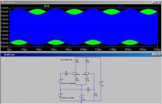
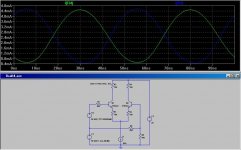
Here is a sim of a typical BJT LTP stage.
Tail current is 5mA, emiter degeneration is 150 ohms. A 500mV rms 20MHz carrier is sitting on top of a 100mV rms 20kHz differential input signal riding on a 1V rms common mode input signal.
The blue and green traces show the collector currents of the BJT's.
The carier is at a consistent amplitude throughout the 20kHz differential input cycle, indicating freedom from overload.
Attachments
lumanauw said:Glen, what happens if the tail current is only 500uA?
Well, as you would expect, at 500uA signal handling ability drops roughly an order of magnitude.
But then again, if you are designing a power amplifier with an LTP tail current of only 500uA you are going to have other more pressing performance issues to be concerned about – and JFETs would give pretty crappy performance at 500uA also.
Low tail current may be an issue for packaged opamp design, where package dissipation and supply current is a concern - but not necessarily for power amplifier design.
To repeat the last line of my first post: Some bipolar input opamp designs with BJT LTP's having very marginal signal handling ability have proven to be good RF detectors, but that doesn't necessarily follow on to amplifier design in general.
IMHO the claim that JFETs must be used in power amplifier inputs to avoid RF rectification/deftection issues is a furphy.
Cheers,
Glen
- Home
- Amplifiers
- Solid State
- Bob Cordell Interview: Negative Feedback