Re: Re: EMI Ingress
Yep, I agree, as long as the bipolar input stage is properly designed as you described. There's just a little more opportunity for it not to be as robust in some design environments.
One of the reasons NFB got its bad rap in the first place was because designers foolishly built amplifiers with undegenerated bipolar input stages. To this day there may be designers out there who do not provide enough degeneration in the misguided quest for lower noise.
Along those same lines, I've sometimes wondered if one the possible benefits of no-NFB amplifier designs is that the designer has no choice but to provide an input stage with very high input voltage-handling dynamic range, since the input stage must handle the full normal input signal level.
Cheers,
Bob
G.Kleinschmidt said:
A properly designed amplifier with a BJT LTP input properly emitter degenerated and running an appropriate tail current (to address other well known design requirements; linearity, TIM, etc) will have a pair of input devices that will linearly operate (ie not rectify, with B-E junctions which remain forward biased) at frequencies well above the broadcast band and well into the HF spectrum with an RF input signal of several hundred mV rms.
JFETs have no real advantage over BJTs here in this regard. And if you are getting more than, say 500mV rms of RF to the input of your amplifier you probably have other things to worry about (JFET or BJT input regardless).
Some bipolar input opamp designs with BJT LTP's having very marginal signal handling ability have proven to be good RF detectors, but that doesn't necessarily follow on to amplifier design in general.
Cheers,
Glen
Yep, I agree, as long as the bipolar input stage is properly designed as you described. There's just a little more opportunity for it not to be as robust in some design environments.
One of the reasons NFB got its bad rap in the first place was because designers foolishly built amplifiers with undegenerated bipolar input stages. To this day there may be designers out there who do not provide enough degeneration in the misguided quest for lower noise.
Along those same lines, I've sometimes wondered if one the possible benefits of no-NFB amplifier designs is that the designer has no choice but to provide an input stage with very high input voltage-handling dynamic range, since the input stage must handle the full normal input signal level.
Cheers,
Bob
G.Kleinschmidt said:Here is a sim of a typical BJT LTP stage.
Tail current is 5mA, emiter degeneration is 150 ohms. A 500mV rms 20MHz carrier is sitting on top of a 100mV rms 20kHz differential input signal riding on a 1V rms common mode input signal.
The blue and green traces show the collector currents of the BJT's.
The carier is at a consistent amplitude throughout the 20kHz differential input cycle, indicating freedom from overload.
Nice work, Glenn. You're preaching to the Choir 🙂.
Cheers,
Bob
For example, If EMI is getting in and messing with the circuits enough to impair the sonics, why can’t we hear artifacts of the EMI in the loudspeaker?
Could not the EMI be modulating (super imposing on) the 'audio' signal (when the audio signal is present) without being rectified (by itself) and thus not be audible by itself?
myhrrhleine said:
Could not the EMI be modulating (super imposing on) the 'audio' signal (when the audio signal is present) without being rectified (by itself) and thus not be audible by itself?
This is a very good question. I think it gets to the heart of the matter.
The question I posed was essentially, "if EMI is present in a sufficient amplitude to affect the sonics, would it also not be audible as noise or garbage at the loudspeakers in the absence of the music?"
It's certainly fair to argue that a constant-amplitude sinusoidal RF EMI source would likely be inaudible, as any nonlinearity it encountered might just result in perhaps a dc offset at some points in the system. Then, when music was also passing through the system, it would have something to intermodulate with that could result in sidebands in the audio band.
However, I would think that most EMI sources have modulation on them or a broadband noise nature that would likely result in sidebands in the audio band when they encountered any nonlinearity in the audio system, even in the absence of audio program material.
BTW, if they did not encounter any nonlinearity in the system, one must come up with a different argument as to how they affect the sound by their presence.
The cell phone making noise in the cheap computer speakers is a good example. Most radio transmissions, if they encounter an audio system with nonlinearities, will demodulate into some kind of audible garbage.
Another example that I am not sure of is that of EMI from switching power supplies. That is certainly a likely culprit out there today. Is the nature of this EMI such that if it encounters a nonlinearity in the audio chain, it will create an audible artifact in the absence of audio program material? Are the radiations from switching supplies even big enough to do something like this in any reasonable setup? Ditto for compact flouorescent lights and lamp dimmers.
Cheers,
Bob
Re: EMI Ingress
Another reason expressed, at least by Leach, against using lead compensation across the feedback resistor is that it is used to correct for a lag in the output stage, which is load dependent, and is therefore unreliable if the load impedance changes.
Bob Cordell said:
4) I never use a lead compensation capacitor across the feedback resistor; such a capacitor greatly increases the coupling of garbage at the output terminals back to the input stage.
Cheers,
Bob
Another reason expressed, at least by Leach, against using lead compensation across the feedback resistor is that it is used to correct for a lag in the output stage, which is load dependent, and is therefore unreliable if the load impedance changes.
Re: EMI Ingress
Hmmmm....... a miller compensated VAS is essentially an integrator, which basically kills RF that finds itself mixed up with the input signal (consider a miller compensated VAS connected to that BJT LTP I simulated earlier).
I think that it is arguably easier to effectively filter the low current supply rails of a power amplifier for RF currents than it is to practically eliminate them from the input signal, so I’d put a question mark over that design strategy too.
Cheers,
Glen
Bob Cordell said:6) I design the amplifier-proper to have very high natural PSRR out to fairly high frequencies. This includes trying to use feedback compensation that does not degrade HF PSRR.
Hmmmm....... a miller compensated VAS is essentially an integrator, which basically kills RF that finds itself mixed up with the input signal (consider a miller compensated VAS connected to that BJT LTP I simulated earlier).
I think that it is arguably easier to effectively filter the low current supply rails of a power amplifier for RF currents than it is to practically eliminate them from the input signal, so I’d put a question mark over that design strategy too.
Cheers,
Glen
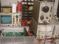
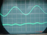
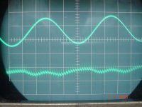
This is the waveform with an operating SMPS nearby. Note that the SMPS garbage seems don't appear signal itself, but appears clearly after the signal is nulled by distortion meter.
But I don't investigate how the mess enters the system at that time. So, I don't know whether it is entering via input, or via output, or via supply, or via something else?
But I don't investigate how the mess enters the system at that time. So, I don't know whether it is entering via input, or via output, or via supply, or via something else?
Attachments
Re: Re: EMI Ingress
Hi Glen,
I am also a strong believer in filtering the supply rails well, but that does not stop me from going the extra mile and trying to design the circuits themselves to have good PSRR out to high frequencies. The amount by which conventional Miller compensation degrades HF PSRR is not a show-stopper, but why put up with it if you don't have to?
Cheers,
Bob
G.Kleinschmidt said:
Hmmmm....... a miller compensated VAS is essentially an integrator, which basically kills RF that finds itself mixed up with the input signal (consider a miller compensated VAS connected to that BJT LTP I simulated earlier).
I think that it is arguably easier to effectively filter the low current supply rails of a power amplifier for RF currents than it is to practically eliminate them from the input signal, so I’d put a question mark over that design strategy too.
Cheers,
Glen
Hi Glen,
I am also a strong believer in filtering the supply rails well, but that does not stop me from going the extra mile and trying to design the circuits themselves to have good PSRR out to high frequencies. The amount by which conventional Miller compensation degrades HF PSRR is not a show-stopper, but why put up with it if you don't have to?
Cheers,
Bob
Hi, Glen,
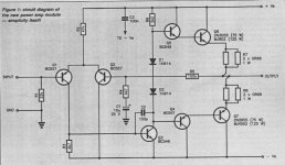
Miller cap around (ordinary connected) VAS worsen PSRR. In this cct, -vs junk will go to R3 , then to base of Q3, then to C2, then goes through output transistors Q5-Q6,Q4-Q7.
There are some "smart" modifications to advoid this. JCX several times mentioned Sackinger paper : http://www.diyaudio.com/forums/showthread.php?s=&threadid=13590&highlight=
http://citeseer.ist.psu.edu/432448.html
Bruno Putzey have a smart one to divert the input of the Cdom from rail referenced node to ground referenced node (slide #34) : http://www.hypex.nl/docs/Bruno Masterclass/slides.htm slide#28-35.
Hmmmm....... a miller compensated VAS is essentially an integrator, which basically kills RF that finds itself mixed up with the input signal (consider a miller compensated VAS connected to that BJT LTP I simulated earlier).
Miller cap around (ordinary connected) VAS worsen PSRR. In this cct, -vs junk will go to R3 , then to base of Q3, then to C2, then goes through output transistors Q5-Q6,Q4-Q7.
There are some "smart" modifications to advoid this. JCX several times mentioned Sackinger paper : http://www.diyaudio.com/forums/showthread.php?s=&threadid=13590&highlight=
http://citeseer.ist.psu.edu/432448.html
Bruno Putzey have a smart one to divert the input of the Cdom from rail referenced node to ground referenced node (slide #34) : http://www.hypex.nl/docs/Bruno Masterclass/slides.htm slide#28-35.
Attachments
lumanauw said:This is the waveform with an operating SMPS nearby. Note that the SMPS garbage seems don't appear signal itself, but appears clearly after the signal is nulled by distortion meter.
But I don't investigate how the mess enters the system at that time. So, I don't know whether it is entering via input, or via output, or via supply, or via something else?
Nice experiment.
What was the signal fundamental frequency and what was the THD reading absent the SMPS. If for example, we are looking at a 0.01% residual, then the level of the SMPS garbage signal is fairly small. Also, it is unclear whether this SMPS noise would be audible at the output of the amplifier. What do you think?
Best,
Bob
Hi, Bob,
The fundamental frequency is 1khz. You can see, the SMPS garbage is about 30khz or so. At that time I just want to see whether HF junk radiation existed or not, and I didn't wrote any note on that experiment. I don't remember how much the THD was. I think the absolute# won't differ much, but the spectra will be different.
With another experiment (not this one), I found out that supersonic frequencies (>20khz up to Mhz) do change the perceived sonics. It is not because we can hear supersonic, but because it is intermodulating/riding the 20hz-20khz signal, making new signals or corrupting signals that is not in the original music.
Janneman made a good point about voltages at input differential. Voltages here are so small, that a small noise here will be magnified alot at the output node.
Is it possible that the HF junk, beside comes via input, output, rail, also possible to enter directly to the bases of the input differential transistors? Like via PCB tracks connected to those bases acting as an antenna?
lumanauw said:This is the waveform with an operating SMPS nearby. Note that the SMPS garbage seems don't appear signal itself, but appears clearly after the signal is nulled by distortion meter.
But I don't investigate how the mess enters the system at that time. So, I don't know whether it is entering via input, or via output, or via supply, or via something else?
David,
Would it be possible to to the experiment again but this time with the amplifier off? I have had similar experiences where the EMI actually existed in the test equipment or even in the test leads. By nature, this type of interference is hard to pin down and it is not always where you see it

Jan Didden
Jan,
this is only partly good idea. With properly matched cables and well RF designed electronics, wiring and shieldind, one gets BETTER results after switch electronics ON. The reason is, that only after switch on you get proper impedances, especially output impedances. Switched off it is in undefined status, regarding RF.
this is only partly good idea. With properly matched cables and well RF designed electronics, wiring and shieldind, one gets BETTER results after switch electronics ON. The reason is, that only after switch on you get proper impedances, especially output impedances. Switched off it is in undefined status, regarding RF.
Hi, Janneman,
OK, if I set up the measurement set-up in the future, I'll try your suggestion.
I also have difficulties in determining whether a waveform in the scope is the real thing or probing mistakes. In class AB amp it is relatively easier than classD setup to determine which is which. When we make classD amps, many waveforms are from probing mistakes. Frankly, I haven't implemented AN-47 (high speed technique) throughly.
PMA said:Jan,
this is only partly good idea. With properly matched cables and well RF designed electronics, wiring and shieldind, one gets BETTER results after switch electronics ON. The reason is, that only after switch on you get proper impedances, especially output impedances. Switched off it is in undefined status, regarding RF.
PMA: Yes you are right. I *should* have said something like: can you repeat it with the amplifier off and the test lead shorted....
David: I see you are aware of these traps.
Jan Didden
Bob Cordell said:It has been argued in the "feedback question/clarification thread" that the application of negative feedback to amplifier circuits creates new, higher-order distortion products, or increases those already present.
Bob,
I took this opportunity and measured the PGP amp behaviour; no doubts, the PGP amp qualifies as "high feedback" 🙂
The 19KHz signal was generated by a PM5193 function generator, while the 20KHz signal was generated by the HP3562A analyzer. Both signals were 2.600 Vpeak-peak into 50ohm, the PGP gain is measured 28.94dB. Therefore, the output reference (0dB level) was 12.87Veff.
Pretty difficult task mainly because, as also mentioned on the PGP web site, the spectral purity of both test signals and the instruments output stages linearity is pretty poor, resulting in numerous artifacts. Mixing the signals in a AD797, LT1115 or LM4562 did help, but substracting the opamp distortion and noise contributions was very difficult so I gave up this path... Using the Amber 5500 signal (very low distortion) was not an option as well - the 50ohm output stage (I have the high output level option) has a very poor linearity.
Finally, direct dual channel (amp input/amp output) measurements and carefully calibrating the channels gains allows (after normalizing the signals) substracting the spectra and extracting the PGP amp contribution. Averaging was set to 1024 and triggering was always set on the amp input signal.
Here are the results:
F[KHz] Level [dB]
----------------------------------
13 -111.50
14 -105.02
15 -106.23
16 -104.81
17 -110.98
18 -111.42
Unfortunately, the HP3562A spectrum analyzer is limited to 100KHz BW with a frequency span of maximum 50KHz , so I canot measure independently the 19/20KHz single tone 5th harmonic and up. Because of this limitation, I have to admit I am not sure how to interpret the measured absolute values and to correlate them with other measurements. In particular I am not sure how to quatitatively correlate the 18KHz component with the 3rd harmonic single tone measurements (the single tone 20KHz 3rd harmonic measures under -120dB) but looking at the relative values they seem to confirm the hypothesis of creation of new, higher-order distortion products, or increasing those already present. The highest component seems to be related to the 7th harmonic.
Re: Re: Re: EMI Ingress
Hi Bob
I'm only (vaguely) defining some of the pros and cons. A Miller compensated VAS would need a much bigger RF input signal to be driven into overload than would a non Miller compensated VAS.
Cheers,
Glen
Bob Cordell said:Hi Glen,
I am also a strong believer in filtering the supply rails well, but that does not stop me from going the extra mile and trying to design the circuits themselves to have good PSRR out to high frequencies. The amount by which conventional Miller compensation degrades HF PSRR is not a show-stopper, but why put up with it if you don't have to?
Cheers,
Bob
Hi Bob
I'm only (vaguely) defining some of the pros and cons. A Miller compensated VAS would need a much bigger RF input signal to be driven into overload than would a non Miller compensated VAS.
Cheers,
Glen
Imd
Hi Ovidiu,
So you didn't use a mixer, right?
I'm not sure what you mean by "direct dual channel ... measurements".
I guess -at the risk of additional IMD inside the signal generators- that you mixed the signals by paralleling the generator outputs (probably via series resistors), right?
Cheers, Edmond.
syn08 said:[snip]
Mixing the signals in a AD797, LT1115 or LM4562 did help, but substracting the opamp distortion and noise contributions was very difficult so I gave up this path...
Hi Ovidiu,
So you didn't use a mixer, right?
[snip]
Finally, direct dual channel (amp input/amp output) measurements and carefully calibrating the channels gains allows (after normalizing the signals)
[snip]
I'm not sure what you mean by "direct dual channel ... measurements".
I guess -at the risk of additional IMD inside the signal generators- that you mixed the signals by paralleling the generator outputs (probably via series resistors), right?
Cheers, Edmond.
- Home
- Amplifiers
- Solid State
- Bob Cordell Interview: Negative Feedback