Hi Andy,
Your proposal is the combined method I was talking about, just put in other words, isn't it?
- Klaus
Your proposal is the combined method I was talking about, just put in other words, isn't it?
- Klaus
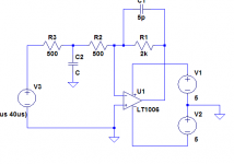
Ah, OK, one can see things from various prespectives. Your schematic hits exactly what I meant, R2+C2 is the series RC from IN- to IN+ (with the latter ==GND), from the noise gain comp perspective (which would amount to +5 for HF in this example). The differences to real noise gain comp are floating, so to say. Depends on at which point along R2 one chooses to attach R3. Full left (as it is now, filtering and noise gain increase) vs. full right (which would be true noise gain comp, no signal gain change or filtering). C1 was left out in this "analysis", though (but would be useful in a practical circuit to add a pole and/or compensate the stray-C zero, while the noise gain comp would increase the gain available to be rolled off with this cap before gain hits 0dB)
- Klaus
- Klaus
Oh, I see what you're saying. I've always thought of this only in terms of being an input LPF. I never really thought of it as frequency compensation before. Good point.
OK, done some further tweaking to my hybrid fully differential opamp (schematic provided a few posts back) using the lead-lag compensation scheme proposed by you guys. I have applied symmetrically to both NFB paths. The pair of Ri shunt capacitors allowed a dramatic reduction in the miller compensation capacitance and did wonders for the slew rate and overall THD.
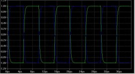
Below 100kHz square wave response of the differential outputs. It was generated with a single ended square wave input.
The green trace is of the output connected to the shunt feedback side. A remaining, but very slight and neglible feed-forward spike at the beginning of each transition can still be seen.
Attachments
And here it is the differential outputs, driven single-ended with a 20kHz sinewave.
This circuit, driven with a hybrid buffer to give a decent input impedance, will provide the differential input drive signals for my monster bridged class A power amp. The valve lineup will look rather cool, protruding from the top of the amps 1.5 meter tall heatsink tower, just above the green phosphor round signal monitoring oscilloscope CRT 😀
I’m using the generic triode models developed by Duncan Amplifiers, which seem to be quite accurate.
THD-20 results are as follows (THD measured differentially, 4Vpp):
Code:
Harmonic	Frequency	 Fourier 	Normalized	 Phase  	Normalized
 Number 	  [Hz]   	Component	 Component	[degree]	Phase [deg]
    1   	2.000e+04	3.993e+00	1.000e+00	  177.80°	    0.00°
    2   	4.000e+04	2.578e-07	6.458e-08	   -3.60°	 -181.40°
    3   	6.000e+04	2.581e-07	6.464e-08	  -85.25°	 -263.05°
    4   	8.000e+04	9.518e-09	2.384e-09	  -38.96°	 -216.76°
    5   	1.000e+05	6.326e-09	1.584e-09	  130.66°	  -47.14°
    6   	1.200e+05	3.173e-09	7.947e-10	   96.00°	  -81.80°
    7   	1.400e+05	7.021e-09	1.758e-09	   90.13°	  -87.67°
    8   	1.600e+05	4.911e-09	1.230e-09	   84.46°	  -93.34°
    9   	1.800e+05	7.399e-09	1.853e-09	 -108.04°	 -285.84°
   10   	2.000e+05	5.822e-09	1.458e-09	  -85.23°	 -263.03°

Total Harmonic Distortion: 0.000009%
Attachments

G.Kleinschmidt said:The valve lineup will look rather cool, protruding from the top of the amps 1.5 meter tall heatsink tower, just above the green phosphor round signal monitoring oscilloscope CRT 😀
Sounds pretty wild! 🙂
andy_c said:
Sounds pretty wild! 🙂
Thanks!
For those who may be interested, I've found a good paper discussing these compensation schemes:
http://focus.ti.com/lit/an/sloa020a/sloa020a.pdf
Go to the bottom of page 23 (item 9) for this type of lead-lag compensation.
Cheers,
Glen
Yesterday I attended an interesting experiment.
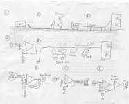
In fig.1, we compare the effect of lifting speaker cables. (A) is when a speaker cable (2m) lying on the floor. (B) is when the same speaker cable is lifted about 15cm from floor.
I can hear a difference. When the speaker cable is hovering in the air, the sound become cleaner, more tight. Then I ask myself, what is the reason. A friend suggested 2 possibilities, one is vibration. This reason doesn't make any sense to me, since nothing is vibrating the cable. Then comes the 2nd possibility, the floor static charge. This makes sense, and in high-speed computer/data centrals, all cables are usually lifted from ground to advoid static charges.
Then I think further. NP said that a transistor is blind, it don't know how it is being used. I guess the same goes to opamp/amplifier. It don't know how it is being used, and don't know which is music signal, which is not.
Imagine fig.2. An amp is powering a loudspeaker, but with 10m speaker cable. In this 10m journey, this cable has to cross to a power gen-set, and some SMPS. They all radiating through the cables, making junk voltage between (+) and (-) of cables because of electromagnetic field.
Then we can replace 2(A) with 2(B). An amp is headed with music signal on its (+) input and junk generator on its output node. Like it or not, this junk generator will enter the (-) input of the amp, because it is the same path with feedback.
Here's the problem. The amp don't know which signal is which. It cannot do "only amplify the music signal, ignore the junk", because the input impedances of the (+)input and (-)input is about the same, the amp will process both signals entering both inputs.
To advoid this, if the junk is high enough, we can put output inductor before the signal leaving the amp. Or we can put a power buffer, which the feedback is taken before this output buffer.
Is there any way that in practical application, one (feedback) amp is intelegent enough to process only the music, not the junk, without output inductor or power buffer in its output?
Attachments
Lumanuaw,
interesting experiment (tried this also years ago, without result -- solid wooden floor).
Today, with so much RF flying around, some RF isolation deems necessary. At least a common mode choke is good thing to have. Then, use twisted pair cable (or something constructed similar in principle), probably shielded (which requires the speaker to be at least partly shielded and the shield made accessible). Terminate the cable for RF with its characteristic impedance if you want to go further.
Many amps do not explicitly tap off feedback for RF frequencies right at the output but from an earlier stage, like e.g. Edmond Stuart's TMC (transitional miller compensation), or see the Leach amp. The stages may get more and more local feedback with rising frequency, while global feedback may be reduced at the same time.
The power buffer will not change anything significantly if it is a feedback design itself, if it is without FB not much of the junk will indeed feed through to the input. The SPLIF-scheme does that, for example. Also one can split the feedback in two parts, one that handles the output voltage but is blind for current and another one which handles the current.
This all brings me to a point that might be considered in the known debate: The "sound" of an amp with global feedback might be strongly influenced by the way the global feedback degenerates with rising frequency combined with an corresponding change in local feedback....
- Klaus
Here is the final circuit (with the necessary voltage clamps to keep the high voltages for the tubes under control) using the lead-lag compensation scheme.
I have improved the colour scheme and used a GIF file to make Edmond and Klaus happy 😀
At 8Vpp (differential) output (to the 9th harmonic):
THD-20k:
0.000023%
THD-10k:
0.000011%
THD-1k:
0.000008%
THD-100Hz:
0.000007%
I have improved the colour scheme and used a GIF file to make Edmond and Klaus happy 😀
At 8Vpp (differential) output (to the 9th harmonic):
THD-20k:
0.000023%
THD-10k:
0.000011%
THD-1k:
0.000008%
THD-100Hz:
0.000007%
Attachments

Hi, PMA,
If the cable impedance factor (50ohm, 75ohm, etc) being neglected, will a very low impedance preamp (with big current drive capability) make a difference? In case of the differential is confused between music signal to (+) input and junk at (-) input (because the input impedances of both is about the same), this low impedance preamp drive will be superior/dominating the input differential (because the junk has much higher output impedance)? Or the situation will be the same with any preamp?
Hi, KSTR,
If you look at Nelson Pass' Statis amp or Nakamichi, the final stages are power buffers, in my opinion. Yes, the SPLIFF topology makes sense in this POV.
I'm about to make another experiment 😀 From classD, I learned that a group delay is important for selfoscilation. When an amp is given square signals, and the feedback resistor is removed, the output square will be delayed towards input square. This delay is frequency dependant. In this openloop, the squares will look normal.
Interesting thing is when the feedback is closed (by putting back the feedback resistor). The output delay will be decreasing much, but the squares will be modified with oscilation problem shapes. There's a trade in this.
Phase_Accurate recently post this link : http://www.diyaudio.com/forums/showthread.php?postid=1310284#post1310284urate
>This makes sense, and in high-speed computer/data centrals, all >cables are usually lifted from ground to advoid static charges.
Hmmm, news to me. I thought false floors are used in order to keep the wiring out of the way. I would be interested in any plausable mechanism for a static field to effect the signals other than outright discharge.
Hmmm, news to me. I thought false floors are used in order to keep the wiring out of the way. I would be interested in any plausable mechanism for a static field to effect the signals other than outright discharge.
Arcing over because of really high voltages... kilovolts... can kill electronics. I sometimes use a hardcore ESD test, the voltage pulse from the piezo unit of a lighter, most equipment does not survive this pulse which has quite some energy (you dont want to get zapped by this discharge, for sure).
Klaus
Klaus
lumanauw said:Hi, Mr. Wurcer,
What is "outright discharge"? Can this affect audio frequencies?
I meant static discharge, the kind that damages IC's and make pops and clicks. I remember Enid Lumley used to drape wet towels around her listening room to prevent charge on the walls and drapes, etc. Personally I find this stuff audio folklore, amusing and harmless.
These products makes money out of this kind of issue.
http://www.6moons.com/audioreviews/furutech6/destat.html
http://www.6moons.com/audioreviews/furutech5/demag.html
http://www.6moons.com/audioreviews/furutech6/destat.html
http://www.6moons.com/audioreviews/furutech5/demag.html
- Home
- Amplifiers
- Solid State
- Bob Cordell Interview: Negative Feedback