syn08 said:
For a PhD degree, usually you have to pass two exams and then write two (defended) dissertations, then you write the thesis and defend it. Publishing the dissertations and the thesis on the web is one of the defending methods.
The exact requirements do differ per country.
If I'm not mistaken there are no exams required (for a PhD) in the Netherlands, but you do have to write a thesis and defend it before a panel (in public, this also differs per country). I think you also have to have a number of (peer reviewed) publications, although I'm not sure if that is a 'hard' requirement or something that the individual universities require.
Remco
Sorry for the deviation from the topic 😀
Edmond Stuart said:
Why?
Well, maybe it is my ignorance, but wouldn't you expect a thesis towards a degree in Philosophy to have some bearing on the art of Philosophy rather than electrical engineering?
Or can I do a thesis on group associations in forum communities and have that count towards a degree in High-energy particle physics? 😉
Jan Didden
ignorance
Hi Jan,
Doctor of Philosophy, abbreviated Ph.D., applies to graduates in a wide array of disciplines, including math and physics.
Cheers, Edmond.
janneman said:Well, maybe it is my ignorance, but wouldn't you expect a thesis towards a degree in Philosophy to have some bearing on the art of Philosophy rather than electrical engineering?
Or can I do a thesis on group associations in forum communities and have that count towards a degree in High-energy particle physics? 😉
Jan Didden
Hi Jan,
Doctor of Philosophy, abbreviated Ph.D., applies to graduates in a wide array of disciplines, including math and physics.
Cheers, Edmond.
janneman said:
Well, maybe it is my ignorance, but wouldn't you expect a thesis towards a degree in Philosophy to have some bearing on the art of Philosophy rather than electrical engineering?
Or can I do a thesis on group associations in forum communities and have that count towards a degree in High-energy particle physics? 😉
Jan Didden
The philosophy bit is in the ability to reflect on the field it applies to, and trying to reach a bigger understanding of it.
Another meaning of philosophy is probably more appropriate for the Ph in PhD: the pursuit of wisdom.
So getting a PhD in EE presumably means you have achieved some degree of wisdom with regard to electrical engineering (at least in an ideal world).
Doing a thesis on group associations in forum communities would therefore not get you a PhD in High-energy particle physics, it might get you one in social science though 😉
Remco
Input/Output Phase Shift with NFB
PMA,
I also have noticed a similar phenomenon when comparing the simulated output signals of a 1st stage diff amp. Even though the input and output signals are in phase, the signals seen on the collectors of the two sevices are out of phase, and this is true even at the relatively low frequency of 1 KHz. Moreover, the phase difference is not exactly 90 degrees.
As an experiment I replaced the FET current source with an ideal SPICE current source, and voila! the phase difference on the two diffamp transistors went to zero. It appears that a non ideal current source introduces a small AC common mode voltage variation that can be seen by observing the voltage wrt ground at the junction of current source and the diffamp emitter resistors. This common mode AC voltage variation seems to modulate the Vbe signals on the diffamp inputs and appears as a differential phase shift on the output.
In terms of distortion, however, the phase shift does not appear to introduce any significant impairment in performance. For example, the simulated SNR increased by only a dB or so from -120 to - 119 dB. (No thermal noise components were included in the simulation.)
Has anyone else investigated this phenomenon?
PMA said:Today we had interesting discussion on our local forum and I have realized that some designers do not understand the fact that input differential voltage / v👎 - v(i) / of amplifier with 1 dominant pole OLG response is 90 degrees phase shifted from output voltage / v(out) /, almost everywhere where openloop gain plot A(w) decreases with -20dB/decade slope. This may cover frequency range like 100Hz - 100kHz, e.g.. I hope it is obvious and I add the illustrating image.
PMA,
I also have noticed a similar phenomenon when comparing the simulated output signals of a 1st stage diff amp. Even though the input and output signals are in phase, the signals seen on the collectors of the two sevices are out of phase, and this is true even at the relatively low frequency of 1 KHz. Moreover, the phase difference is not exactly 90 degrees.
As an experiment I replaced the FET current source with an ideal SPICE current source, and voila! the phase difference on the two diffamp transistors went to zero. It appears that a non ideal current source introduces a small AC common mode voltage variation that can be seen by observing the voltage wrt ground at the junction of current source and the diffamp emitter resistors. This common mode AC voltage variation seems to modulate the Vbe signals on the diffamp inputs and appears as a differential phase shift on the output.
In terms of distortion, however, the phase shift does not appear to introduce any significant impairment in performance. For example, the simulated SNR increased by only a dB or so from -120 to - 119 dB. (No thermal noise components were included in the simulation.)
Has anyone else investigated this phenomenon?
/OT on
Edmond, Rambi, thanks, it was indeed my ignorance. No Ph.D in High Energy Particle Physics for me. So close!
Thanks,
/OT off
Jan Didden
Edmond, Rambi, thanks, it was indeed my ignorance. No Ph.D in High Energy Particle Physics for me. So close!
Thanks,
/OT off
Jan Didden
Re: Input/Output Phase Shift with NFB
Do you have results for a resistor tail?
analog_guy said:
PMA,
I also have noticed a similar phenomenon when comparing the simulated output signals of a 1st stage diff amp. Even though the input and output signals are in phase, the signals seen on the collectors of the two sevices are out of phase, and this is true even at the relatively low frequency of 1 KHz. Moreover, the phase difference is not exactly 90 degrees.
As an experiment I replaced the FET current source with an ideal SPICE current source, and voila! the phase difference on the two diffamp transistors went to zero. It appears that a non ideal current source introduces a small AC common mode voltage variation that can be seen by observing the voltage wrt ground at the junction of current source and the diffamp emitter resistors. This common mode AC voltage variation seems to modulate the Vbe signals on the diffamp inputs and appears as a differential phase shift on the output.
In terms of distortion, however, the phase shift does not appear to introduce any significant impairment in performance. For example, the simulated SNR increased by only a dB or so from -120 to - 119 dB. (No thermal noise components were included in the simulation.)
Has anyone else investigated this phenomenon?
Do you have results for a resistor tail?
Open loop bandwidth
This was originally posted in the feedback question/clarification thread.
Hi John,
You raise a couple of interesting points here. They have been debated many times. But let's play along for a moment.
Suppose it is open loop bandwidth and that it is not NFB per se. This seems to fit in with Otala's original assertions. It's been a long time since I've read his stuff, but I think he was against high amounts of negative feedback largely because at the time I think he always associated high NFB with low open loop bandwidth. So maybe he was more against low open loop bandwidth than against high NFB. If one could achieve 20 kHz open loop bandwidth with 40 dB of NFB out to 20 kHz, maybe he was not even against that amount of NFB.
Then there are the issues of what we can measure and what we can't measure (or which we have not yet figured out how to measure). I hope that you are not asserting that low open loop bandwidth causes increased TIM or PIM. This has been shown to be simply not the case, by measurement, not just by theory.
Perhaps, on the other hand, you just have a hunch that open loop bandwidth is the issue, and maybe we just don't know why. That's OK. That's the X-factor that I always try to allow for.
Here is a possibility, for example. In an amplifier with wide open loop bandwidth, the error signal within the amplifier, at least in the input stage, is largely in phase with the input signal, and is somewhat a replica of the input signal. On the other hand, the error signal in an amplifier with low open loop bandwidth is largely 90 degrees out of phase with the main signal, due to the integrating nature of the forward path of the amplifier. Indeed, the error signal prior to the integrating action of the compensation is more like a replica of the derivative of the input signal.
If the stage where the error signal and the input signal are together this way is nonlinear, the nature of the distortion produced will be different depending on whether the input signal is intermodulating with a normal replica of itself or a differentiated replica of itself. The spectral interactions will be quite different.The distortion thereby produced, if audible, could be expected to sound different.
Note that I used the term different, not better or worse. Also note that we assume that the closed loop bandwidth of both amplifiers is the same. This means that the lower open loop bandwidth gets that way as a result of higher open loop gain at lower frequencies. This further means that the error signal in the low open loop bandwidth amplifier looks more like a differentiated version of the input signal because it has a reduced low frequency content, not because it has increased high frequency amplitudes. Put another way, in the low-open-loop-bandwidth amplifier, the peak value of the error signal at the input may be the same, but the rms value of the error signal will be quite a bit smaller.
Would distortion measurements of these two amplifiers be different? Maybe. THD-20 would probably be about the same.
Odd-order CCIF spectra would probably be similar. Even order CCIF spectra down around 1 kHz might be lower in the amp with low open loop bandwidth due to higher feedback at lower frequencies. SMPTE IM would probably be lower in the amp with lower open loop bandwidth again due to higher feedback at low frequencies.
Finally, it is interesting to note that the processing of differentiated signals in the presence of a nonlinearity also very much takes place in the LP as a result of the integrating effect of the RIAA equalization.
Cheers,
Bob
This was originally posted in the feedback question/clarification thread.
john curl said:
I suspect that high open loop bandwidth, coupled with feedback is as non-problematic as local feedback, because both have equal feedback over the audio range and more. I bet that the fundamental problem is low open loop bandwidth.
It may not be just feedback that is the real problem. I think it is OPEN LOOP BANDWIDTH, get it above 25KHz or so, and there should be no problem with modest amounts of feedback.
Hi John,
You raise a couple of interesting points here. They have been debated many times. But let's play along for a moment.
Suppose it is open loop bandwidth and that it is not NFB per se. This seems to fit in with Otala's original assertions. It's been a long time since I've read his stuff, but I think he was against high amounts of negative feedback largely because at the time I think he always associated high NFB with low open loop bandwidth. So maybe he was more against low open loop bandwidth than against high NFB. If one could achieve 20 kHz open loop bandwidth with 40 dB of NFB out to 20 kHz, maybe he was not even against that amount of NFB.
Then there are the issues of what we can measure and what we can't measure (or which we have not yet figured out how to measure). I hope that you are not asserting that low open loop bandwidth causes increased TIM or PIM. This has been shown to be simply not the case, by measurement, not just by theory.
Perhaps, on the other hand, you just have a hunch that open loop bandwidth is the issue, and maybe we just don't know why. That's OK. That's the X-factor that I always try to allow for.
Here is a possibility, for example. In an amplifier with wide open loop bandwidth, the error signal within the amplifier, at least in the input stage, is largely in phase with the input signal, and is somewhat a replica of the input signal. On the other hand, the error signal in an amplifier with low open loop bandwidth is largely 90 degrees out of phase with the main signal, due to the integrating nature of the forward path of the amplifier. Indeed, the error signal prior to the integrating action of the compensation is more like a replica of the derivative of the input signal.
If the stage where the error signal and the input signal are together this way is nonlinear, the nature of the distortion produced will be different depending on whether the input signal is intermodulating with a normal replica of itself or a differentiated replica of itself. The spectral interactions will be quite different.The distortion thereby produced, if audible, could be expected to sound different.
Note that I used the term different, not better or worse. Also note that we assume that the closed loop bandwidth of both amplifiers is the same. This means that the lower open loop bandwidth gets that way as a result of higher open loop gain at lower frequencies. This further means that the error signal in the low open loop bandwidth amplifier looks more like a differentiated version of the input signal because it has a reduced low frequency content, not because it has increased high frequency amplitudes. Put another way, in the low-open-loop-bandwidth amplifier, the peak value of the error signal at the input may be the same, but the rms value of the error signal will be quite a bit smaller.
Would distortion measurements of these two amplifiers be different? Maybe. THD-20 would probably be about the same.
Odd-order CCIF spectra would probably be similar. Even order CCIF spectra down around 1 kHz might be lower in the amp with low open loop bandwidth due to higher feedback at lower frequencies. SMPTE IM would probably be lower in the amp with lower open loop bandwidth again due to higher feedback at low frequencies.
Finally, it is interesting to note that the processing of differentiated signals in the presence of a nonlinearity also very much takes place in the LP as a result of the integrating effect of the RIAA equalization.
Cheers,
Bob
Re: Open loop bandwidth
While from a system standpoint, and under normal engineering rules we are familiar with, both approaches should make no difference.
Yet in this particular field we are dealing with ppm issues which arguably may be hearable. Under this circumstances what you exposed makes perfect sense.
Rodolfo
Bob Cordell said:This was originally posted in the feedback question/clarification thread.
........
Would distortion measurements of these two amplifiers be different? Maybe. ......
While from a system standpoint, and under normal engineering rules we are familiar with, both approaches should make no difference.
Yet in this particular field we are dealing with ppm issues which arguably may be hearable. Under this circumstances what you exposed makes perfect sense.
Rodolfo
still I understand the bad feelings against the phase shift, but is this really evil?
Feedback seems to work anyway and as I vaguely remember control theory, it calls for integration. 😕
Regards
Feedback seems to work anyway and as I vaguely remember control theory, it calls for integration. 😕
Regards
G'day
A slight change of topic.
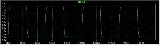
Does anyone know how to eliminate the square wave overshoot that seems to be inherent when using shunt feedback around and opamp, as opposed to series feedback - or know of a good reference explaining the mechanism behind the problem??????
Below is the simmed results for a miller compensated discrete opamp with a 1MHz fT and a phase margin of 80 deg.
I've got the THD-20 of my single ended to differential hybrid (2 * 12AX7 + 2 * 6SN7GTB) linedriver down to 0.3ppm, but the overshoot on the shunt feedback path/side is giving me grief.
Cheers,
Glen
A slight change of topic.
Does anyone know how to eliminate the square wave overshoot that seems to be inherent when using shunt feedback around and opamp, as opposed to series feedback - or know of a good reference explaining the mechanism behind the problem??????
Below is the simmed results for a miller compensated discrete opamp with a 1MHz fT and a phase margin of 80 deg.
I've got the THD-20 of my single ended to differential hybrid (2 * 12AX7 + 2 * 6SN7GTB) linedriver down to 0.3ppm, but the overshoot on the shunt feedback path/side is giving me grief.
Cheers,
Glen
Attachments

OK, I’ve worked the mechanism out. I guess that it should have been obvious. It is due to current being delivered to the load via the actual shunt feedback network from the actual source for the brief period of time that the opamp goes open loop on the square wave transition.
This is obviously something that cannot be eliminated with shunt feedback, only minimised.
The simplest way to do so is to bandwidth limit the input signal. Limiting the input signal to about 1/3 the unity feedback gain transition seems to reduce the overshoot to totally neglible levels.
Below is the result for shunt feedback with the input square wave bandwidth limited to 330kHz (1MHz miller compensated fT) which would seem more than ample for audio reproduction.
Attachments
Feedforward troughput (resistive network), the virtual ground not so fast to fix it. Try very small capacitor.
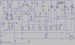
Hmmm…..OK. Where exactly should I put a small capacitor? I’ve tried on just about everywhere to no avail - both on the circuit below and simulations using common opamps, which all exhibit the exact same problem (to varying degrees) when using shunt feedback.
Attachments
PMA said:Across the feedback resistor, to compensate for -IN stray capacitance.
Tried that, it doesn't work - it actually makes it slightly worse (transient input current is now bypassed directly to the output without being attenuated by Rf) You can try to compensate for the stray input capacitance but you can't eliminate the amplifiers propagation delay 🙁 The overshoot I’m getting is about 70nS in duration.
OK, I have made a quick and dirty LTspice sim to demonstrate the phenomenon I am talking about.
The sim uses one of the opamps provided in the LT spice library, configured with -6dB of gain using shunt feedback and feed with a fast rise time square wave.
The overshoot at the beginning of each high-low and low-high transition can be clearly seen. It is due to direct coupling of the input signal via Ri and Rf to the output (attenuated by the finite HF output impedance of the opamp) before the opamp has a chance to react due to it’s internal propagation delay. I have also included a shunt capacitor across Rf. It can be seen that any value of shunt capacitance here is to be avoided as it improves the coupling of the input signal to the output.
To allow it to be posted at an attachment the LTspice *.asc file has been renamed with a *.txt extension. Delete this to use it.
Attachments
Glen, you might also try a noise gain degeneration (lead-lag compensation). This scheme partially shunts the feed-forward feedtrough, plus it can be also altered to additionally roll off the input at the same time which one usually needs anyway. Of course it has maximum benefit only with circuits/opamps which are unstable at the desired signal gain and need some compensation anyway.
- Klaus
- Klaus
G.Kleinschmidt said:OK, I have made a quick and dirty LTspice sim to demonstrate the phenomenon I am talking about.
Hi Glen,
How about splitting R2 into two equal series resistors of 500 Ohm and putting a shunt capacitor from their junction to ground? The capacitor could be chosen according to the Leach criterion. That is, the bandwidth and slew rate are such that the amp clips before it slews with a square wave.
- Home
- Amplifiers
- Solid State
- Bob Cordell Interview: Negative Feedback