Yes, it is a very interesting circuit which has to be quite precisely tuned for the output devices type.
PMA said:
Hi Bob,
thank you very much for your simulations. Yes, the NFB is doing the job, but the result is poor /I would rather say very poor/ (5th and 7th about -100dB). In real amplifiers, we can do it much better. For me, the output stage with minimal distortion is the solution. Then, after feedback application, we can get excellent results with almost no high harmonics.
Regards,
Pavel
Hi Pavel,
The question being addressed for which I did the simulations was “what is the effect of NFB on crossover distortion when NFB decreases as a function of frequency, as in a real amplifier”?
That’s all I was trying to show. I think the results of the simulation bear out that NFB is effective against crossover distortion, even when it is rolling off with frequency as a result of compensation.
The results shown are certainly not poor. They are good, but not excellent. They are better than many very good amplifiers out there (especially considering that only one output pair is being simulated here). The results are as follows:
THD-1: 0.0027%
3rd: -94 dB (0.002 %)
5th: -95 dB (0.0018 %
7th: -101 dB (0.0009 %)
15th: -132 dB (0.000003 %)
Note that the amount of feedback I used was just modest, with 34 dB at low frequencies, 20 dB at 20 kHz, and a 4 kHz open-loop bandwidth.
I was deliberately not trying to “grandstand” by using a lot of NFB. Indeed, the amount I used is what I believe to be the amount used by John Curl in his JC-1. I thought that that would be the most relevant for all concerned.
In a subsequent post, I’ll show the spectrum of the distortion for the same output stage when the amount of NFB is 60 dB at low frequencies and 34 dB at 20 kHz, with a 1 kHz open-loop bandwidth and a 1 MHz closed loop bandwidth. This is more typical of what some would describe as a high feedback amplifier.
If you are arguing that it is better to use a Class-A output stage to get lower distortion, of course I agree with you. This is not in the mainstream of amplifier design, however.
If you are arguing that it is better to use error correction in the output stage to get lower distortion, of course I agree with you. This is also not in the mainstream.
If you are arguing that it is better to use multiple output pairs in parallel with a consequently higher total idle bias to get lower distortion, of course I agree with you.
Cheers,
Bob
A bit OT, but I had to share this gem:
"When playing a record or CD there is no such thing as IM distortion. IM distortion can only occur in the recording chain. IM is a result of multiple inputs modulating each other. Conceivably it goes on at the mixing console.
During home playback at any moment in time there is only one voltage occurring which is the vector sum of whatever music was recorded so there can be no IM distortion in the playback chain. Harmonic distortion and other problems but no IM".
Posted by a guy who sells audio and test equipment. Well, I'm glad that I can stop worrying about IMD 😀
Jan Didden
Bob Cordell said:
Hi Pavel,
The question being addressed for which I did the simulations was “what is the effect of NFB on crossover distortion when NFB decreases as a function of frequency, as in a real amplifier”?
That’s all I was trying to show.
Hi Bob,
I am sorry If I sounded too crudely. It was a very good excersising on NFB vs. crossover distortion and I thank you again for it.
I used a bit unhappy notice about the quality of such circuit, of course it was only a school example. You wrote what I meant at the end of your post.
Thanks,
Pavel
john curl said:Too much 7th.
John, you might like something like this? (just kidding - a little bit 😉 )
Attachments
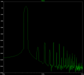
Posted below is the output spectrum result for the previously-mentioned Class-AB output stage, but this time with 60 dB of LF NFB, 34 dB of 20 khz NFB, and a 1 khz open-loop bandwidth.
The summary for the three examples is as follows:
No NFB:
THD: 0.095 %
7th: -75 dB
15th: -112 dB
34 dB/ 20 dB NFB:
THD: 0.0027 %
7th: -101 dB
15th: -132 dB
60 dB/ 34 dB NFB (below example):
THD: 0.00039 %
7th: -116 dB
15th: -146 dB
Cheers,
Bob
The summary for the three examples is as follows:
No NFB:
THD: 0.095 %
7th: -75 dB
15th: -112 dB
34 dB/ 20 dB NFB:
THD: 0.0027 %
7th: -101 dB
15th: -132 dB
60 dB/ 34 dB NFB (below example):
THD: 0.00039 %
7th: -116 dB
15th: -146 dB
Cheers,
Bob
Attachments
estuart said:
Hi John,
Is -114dB of 140kHz too much?
Cheers,
The 7th there was -101dB and IT IS TOO MUCH.
john curl said:Too much 7th.
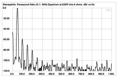
7th order CCIF IM on the JC-1 is only down 99 dB in the Sterophile review. I guess that is too much also 🙂.
Bob

PMA said:The 7th there was -101dB and IT IS TOO MUCH.
Hi John,
I was talking about a different amp, one with TMC, so I ask you again, is the 7th harmonic of 20kHz at -114dB too much?
Cheers
Bob Cordell said:
60 dB/ 34 dB NFB (below example):
THD: 0.00039 %
7th: -116 dB
15th: -146 dB
The SPICE NFB math building block is outstanding! 😉 (just kidding)
Bob Cordell said:
7th order CCIF IM on the JC-1 is only down 99 dB in the Sterophile review. I guess that is too much also 🙂.
Bob
Really -99dB?
lumanauw said:Is the high order harmonics comes out when a device is turned on/ turned off?
Keeping devices in forward bias generally reduces the high order
harmonics, but is no guarantee that they won't be generated.
😎
- Home
- Amplifiers
- Solid State
- Bob Cordell Interview: Negative Feedback