Bob Cordell said:
However, if you are referring to the dual complementary differential input stage arrangement you use in your 12W amplifier, I do not think it is a very good design, but I have not bothered to simulate it, since it appears to be sub-optimal by inspection.
Well thank you very much for the in-depth analysis. Every design is "sub-optimal" to a degree. The design was only intended to be modest improvement over the standard miller-compensated, symetrical topology to see how good it can be made to perform, and it does perform quite well.
I have, for instance, already commented on the fact that the low impedance presented at the base of each VAS transistor (with the reduced NFB) isn't a serious issue due to the high input impedance of the tripple emitter output stage.
The design has been sinulated by Edmond at 8ppm THD-20 at the rated output power into 4 ohms. I have built it an my measurements confirm <0.001% THD 20Hz to 20kHz.
Is that poor?
For a design that only uses bog standard, electronics hobby-store transistors and doesn't resort to the complexities of error correction, fancy feedback methods or nested feedback loops, I think the performance is rather good.
Hi Glen,
This high-power class A approach, is it based on an AES article? If so, do you have the author(s) and/or the title of the article?
This high-power class A approach, is it based on an AES article? If so, do you have the author(s) and/or the title of the article?
G.Kleinschmidt said:
Well thank you very much for the in-depth analysis. Every design is "sub-optimal" to a degree. The design was only intended to be modest improvement over the standard miller-compensated, symetrical topology to see how good it can be made to perform, and it does perform quite well.
I have, for instance, already commented on the fact that the low impedance presented at the base of each VAS transistor (with the reduced NFB) isn't a serious issue due to the high input impedance of the tripple emitter output stage.
The design has been sinulated by Edmond at 8ppm THD-20 at the rated output power into 4 ohms. I have built it an my measurements confirm <0.001% THD 20Hz to 20kHz.
Is that poor?
For a design that only uses bog standard, electronics hobby-store transistors and doesn't resort to the complexities of error correction, fancy feedback methods or nested feedback loops, I think the performance is rather good.
So I take it that the input stage of your 12W amplifier was, after all, what you were referring to?
What is sub-optimal about it, in my opinion, is all that extra circuit junk you hang on it to balance the current drawn by the load resistor on the output of the differential pair. It looks like a waste of circuitry that just adds noise, may make obtaining dc balance of the collector current of the input pair less reliable, and still ends up with the poor current mirror being loaded down by 1 K.
You should post your distortion results on your web page. What THD analyzer do you use?
Cheers,
Bob
Bob Cordell said:
So I take it that the input stage of your 12W amplifier was, after all, what you were referring to?
No. I wasn't referring to any specific symmetrical topology - just ones a little more complex than that of the Hafler or LEach designs discussed earlier. I didn't cite my 12W amp's imput stage as the best out there - just a meagre example.
What is sub-optimal about it, in my opinion, is all that extra circuit junk you hang on it to balance the current drawn by the load resistor on the output of the differential pair. It looks like a waste of circuitry that just adds noise, may make obtaining dc balance of the collector current of the input pair less reliable, and still ends up with the poor current mirror being loaded down by 1 K.
Hi Bob.
Hey, don't hold back. Most of you analysis is wrong though. The VAS biasing scheme ("extra circuit junk" - which is only a few extra transistors, etc) doesn't effect the collector current balance of the diffential pairs, and the VAS idle currents are quite accurately defined by the fixed biasing voltage developed across each LTP load resistor by the current source. This is what I quite like about it. Contributed noise is minimal.
And, yes the LTP's are still loaded down by a 1k resistor, but the I-mirrors effectively double the voltage gain of each LTP and provide push-pull current drive to the VAS miller capacitance, which promotes symetrical slewing and even harmonic cancellation. I think this makes it all worth while.
You should post your distortion results on your web page. What THD analyzer do you use?
OK, so you have no further comment on the rather good simulated results.
My THD anayser which goes this low is home-brew. It is mostly an elaborate bank of filters and low noise amplifiers. ATM, I can make spot measurements at 1,5,10 and 20kHz.
I will be developing this further as part of my 500W amp project, and yes, all this will be going on my web page. ATM the 12W amp is in bits, being built into its chassis (as well as another design). When they are ready, my webpage will be comprehensively updated.
Cheers,
Glen
andy_c said:Hi Glen,
This high-power class A approach, is it based on an AES article? If so, do you have the author(s) and/or the title of the article?
G'day Andy.
Technics did it in a single-ended design in the 80's. They called it class A+. I have found a write-up about it in an "Electronics Australia" magazine. Unfortunately I can't remember which magazine it was, and my EA's have been mixed up with several hundred ETI's I have recently acquired. I will try to find it and scan it ASAP.
Cheers,
Glen
john curl said:Glen, it has been my experience that all else being equal, that complementary differential has about 1/2 the distortion compared to a single differential design. This can be up to 5 times compared to a single diff pair with a single second stage device and a current source as a load.
I have and do build both, but I personally prefer to make overall simpler circuits than you or Bob prefer, if and when possible.
When necessary, such as making a line driver for Sound Technology 25 years ago, that had to have a distortion at 100KHz below .001%, I used an input circuit similar to Bob's, with cascodes everywhere to reduce even small traces of distortion, but I maintained a 100KHz open loop bandwidth, so I used resistive loading on my inputs and 2 pole compensation.
In this case I chose the single diff. pair design to have less nonlinear input capacitance to worry about.
Hi John.
I agree. This is why I have stuck with the symmetrical/complementary LTP input for my over-the-top 500W class A design. I have now finalised this part of the circuit, it is relatively simple and performs better than what I was able to achieve with a symmetrical VAS driven from a single LTP.
I’ll start a new thread on this late this week, starting with a high-res schematic.
Cheers,
Glen
Thanks Glen. No hurry, I was just curious, as I have a large library of AES papers on CD.
BTW, regarding distortion measurement, Renardson has some nice stuff on his pages. There's a nice diagram of a setup here, and his MS thesis on this is here. What's interesting and not immediately obvious is that the nulling of the fundamental over a range of frequencies also cancels out the component of the residual due to the amplified source distortion over that frequency range. He's claiming ability to measure very low distortion with a source that's not nearly as good as what he's trying to measure. He states, "On one occasion I measured distortion components around 0.00001% using a signal generator with over 0.5% t.h.d.". I'm sure this is optimistic, but the principle becomes clear after thinking about the idea a bit.
I'm going to gin up an IM measurement setup using these techniques with some LM4562s.
andy_c said:Thanks Glen. No hurry, I was just curious, as I have a large library of AES papers on CD.
BTW, regarding distortion measurement, Renardson has some nice stuff on his pages. There's a nice diagram of a setup here, and his MS thesis on this is here. What's interesting and not immediately obvious is that the nulling of the fundamental over a range of frequencies also cancels out the component of the residual due to the amplified source distortion over that frequency range. He's claiming ability to measure very low distortion with a source that's not nearly as good as what he's trying to measure. He states, "On one occasion I measured distortion components around 0.00001% using a signal generator with over 0.5% t.h.d.". I'm sure this is optimistic, but the principle becomes clear after thinking about the idea a bit.
I'm going to gin up an IM measurement setup using these techniques with some LM4562s.
Thanks a lot for that. This looks like exactly what I'm after.
Measuring the 500W amp will be as big a project as building it.
I have to go now - back in a day or two.
Cheers,
Glen
G.Kleinschmidt said:
G'day Andy.
Technics did it in a single-ended design in the 80's. They called it class A+. I have found a write-up about it in an "Electronics Australia" magazine. Unfortunately I can't remember which magazine it was, and my EA's have been mixed up with several hundred ETI's I have recently acquired. I will try to find it and scan it ASAP.
Cheers,
Glen
I remember being at the AES convention where that paper was presented, and I always thought it was a neat idea. I'll look forward to seeing your results on it. If I recall correctly, the entire power supply that provides the low-voltage rails to the Class-A core is driven by the output of the Class AB big amplifier. If this is the case, do you anticipate any issues with regard to putting wideband audio on the secondary of a transformer whose primary is at line side? Hopefully, for example, there will not be too much RFI intrusion onto the rails of the Class A core.
Does this mean that you will have to use some kind of special cryogenically-treated single-crystal power cord? 🙂.
What kind of a transformer do you plan to use to power the Class-A core?
Cheers,
Bob
andy_c said:Hi Glen,
This high-power class A approach, is it based on an AES article? If so, do you have the author(s) and/or the title of the article?
"High Efficiency Class A Audio Power Amplifier"
(CLASS A+ AMPLIFIER)
AES Preprint no. 1382 (N-5)
Presented at the 61st Convention
November 3-6, 1978
I don't know if it made it beyond a preprint:
http://www.aes.org/e-lib/browse.cfm?elib=2972
I read it shortly after it came out, and have not looked at it since then. I seem to recall chatting with my brother about it and we agreed that it was a clever idea.
Pete B.
PB2 said:"High Efficiency Class A Audio Power Amplifier"
(CLASS A+ AMPLIFIER)
AES Preprint no. 1382 (N-5)
Presented at the 61st Convention
November 3-6, 1978
Thanks very much Pete! I will look it up.
PB2 said:"High Efficiency Class A Audio Power Amplifier"
(CLASS A+ AMPLIFIER) AES Preprint no. 1382 (N-5)
Presented at the 61st Convention November 3-6, 1978
You might want to look at the patent #4,115,739, Sano, Hirosha,
and Hirota, April 1977.
And you might want to see my patent #5,343,166 which is
related to the subject.
😎
G.Kleinschmidt said:
Bob:
What is sub-optimal about it, in my opinion, is all that extra circuit junk you hang on it to balance the current drawn by the load resistor on the output of the differential pair. It looks like a waste of circuitry that just adds noise, may make obtaining dc balance of the collector current of the input pair less reliable, and still ends up with the poor current mirror being loaded down by 1 K.
Hi Bob.
Hey, don't hold back. Most of you analysis is wrong though. The VAS biasing scheme ("extra circuit junk" - which is only a few extra transistors, etc) doesn't effect the collector current balance of the diffential pairs, and the VAS idle currents are quite accurately defined by the fixed biasing voltage developed across each LTP load resistor by the current source. This is what I quite like about it. Contributed noise is minimal.
And, yes the LTP's are still loaded down by a 1k resistor, but the I-mirrors effectively double the voltage gain of each LTP and provide push-pull current drive to the VAS miller capacitance, which promotes symetrical slewing and even harmonic cancellation. I think this makes it all worth while.
Cheers,
Glen
And another thing or two with regards to noise;
The I-mirror loading of each LTP cancels the noise generated in the LTP tail current sources. The symmetrical topology of the current source (Q3, Q4, R7) that provides the symmetrical VAS biasing voltages across R22 and R25 injects a common noise signal into the base of each VAS transistor. Since the VAS is differential, the noise of this current source is cancelled as well.
I don't see noise being a problem here.
andy_c said:Thanks Glen. No hurry, I was just curious, as I have a large library of AES papers on CD.
OK Andy, check your E-mail.
PB2's reference made it easy to find, I just sorted through my 1978 issues of EA.
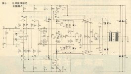
I guess I can't post it up here due to copyright issues, but anyone with a collection of old EA's can find:
"The Strange Case Of the Technics A+ Amplifier"
Page 33
Electronics Australia Magazine
Vol. 39 No. 11 February, 1978
I'm Back!
Hey guys, I'm back from my vacation. I was in the Mediterranian and saw some really beautiful sights that made me wish I had listened more carefully to my history teachers in school 🙂.
I spent the whole day today digging my way out of a stack of emails at work. Now I can look over some of these threads!
Cheers,
Bob
- Home
- Amplifiers
- Solid State
- Bob Cordell Interview: Negative Feedback