Hi Bob,
When you say "look at spectrum at the amplifier input", do you mean the input node or across the differential input (bases/gates) for error wrt to the input node ?
Does this test show up limited open loop gain at higher AF ?
Cheers ..... Graham.
When you say "look at spectrum at the amplifier input", do you mean the input node or across the differential input (bases/gates) for error wrt to the input node ?
Does this test show up limited open loop gain at higher AF ?
Cheers ..... Graham.
Bob Cordell said:
Mike,
Your first paragraph here seems like a reasonable description of the scheme. I agree about the input stage not enjoying the same loop gain boost as with DPC, but I would not then say that the scheme is a complete waste of time and effort. In an amplifier where the biggest distortion problem is in the output stage, and where the designer does not want a DPC global NFB charactersistic, is this scheme not useful?
Cheers,
Bob
No, because the scheme does not increase the amount of feedback applied to the output stage compared with the equivalent DPC at the frequencies of interest.
Moreover, the scheme actually applies a DPC characteristic about the last two stages of the amp.
Therefore, it cannot be usefully claimed that the designer has avoided the use of DPC.
So what's the point?

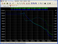
Green Trace: Minor-loop gain about output stage with Edmond's scheme.
Blue Trace: Major-loop gain with equivalent DPC.
You may download the relevant sim circuit here.
Attachments
mikeks said:
No, because the scheme does not increase the amount of feedback applied to the output stage compared with the equivalent DPC at the frequencies of interest.
[
Mike, at this point you are perfectly right. The point is that my scheme isn't plagued by the phase dip at around 20kHz of the global feedback loop (wrt to the input stage), hence a nicer step response.
Cheers,
Hi Mike,
That is an inverse of the sim I posted at #537 above, and it is the reactive nature of the inner loop that can lead to altered tonality when driving reactive dynamic loudspeaker loads; ie. crossovers feeding high mid-bass to tweeter.
THD better but reproduction not.
Cheers ........ Graham.
That is an inverse of the sim I posted at #537 above, and it is the reactive nature of the inner loop that can lead to altered tonality when driving reactive dynamic loudspeaker loads; ie. crossovers feeding high mid-bass to tweeter.
THD better but reproduction not.
Cheers ........ Graham.
estuart said:
Mike, at this point you are perfectly right. The point is that my scheme isn't plagued by the phase dip at around 20kHz of the global feedback loop (wrt to the input stage), hence a nicer step response.
Cheers,
Actually this phase dip is not manifest in the closed-loop response and therefore has no significant effect on your step response.
Additionally, the step response of an amp compensated by whatever means can be trivially tweaked.
Graham Maynard said:Hi PMA,
Quite a spike; +/-1A should not be difficult.
I used to know what would cause all the different deviations and looping error traces, but it looks as though there is an internal failure to adequately control one half of a complementary output stage at crossover.
Yes THD figures are meaningless when load angles become dynamically shifted.
I found your simulated and real world reverse testing of the Symasym interesting. For the real world impedances did not fully invoke the crossover distortions shown in simulation.
In this regard maybe lower accuracies for step size and interpolation would give more realistic results than simulating with maximum resolution.
Hi Rodolfo,
Yes indeed a powerful tool, for if anything shows up here it can only become worse with voltage amplitude swing, as when a fixed potential is applied to the amplifier input.
Or maybe standard 10kHz on amplifier under test input with output being observed, whilst a separate amplifier drives the earthy end of its 8 ohm load at say 100Hz, then try swopping the generators over.
Cheers ........ Graham.
Building on Baxandall's idea, how about exercising the amp input with say, 20Hz, grounding the input for higher frequencies, connecting the load/drive amp through a largish cap (50uF) to block the 20Hz but accept the highish test freq pumped into the output, so the amp is exercised through its full Vo range by the 20Hz while the highish freq exercises it through its current range.
Jan Didden
Graham, howzzat for a single-sentence operating procedure? 😉
Re: Re: Amusing ppm's
Yes indeed! Although I did have 'spiced' designs that show a thd of 0.012ppm at 20kHz and full power, to build such 'pudding' is quite a different story. Of greatest concern were the pcb tracks and leads (the devil!) that might induce distortion too. So, I even designed a small compensating circuit (equipped with potmeters) to nullify these effects afterwards. It was a challenging exercise to rival Halcro, but, as I'm retired, this thing will be never build.
Cheers,
ingrast said:
Edmond,
So we agree simulation results must be interpreted in proper context.
They obviously excel for testing concepts (and save charred silicon), and for comparative evaluation of alternatives as long as one does not go all the way to expect -180 dB performance just because the simulator says so.
As Bob has hammered countles times, "the proof is in the pudding" and "the devil is in the details", i.e. a real, working measured circuit.
Rodolfo
Yes indeed! Although I did have 'spiced' designs that show a thd of 0.012ppm at 20kHz and full power, to build such 'pudding' is quite a different story. Of greatest concern were the pcb tracks and leads (the devil!) that might induce distortion too. So, I even designed a small compensating circuit (equipped with potmeters) to nullify these effects afterwards. It was a challenging exercise to rival Halcro, but, as I'm retired, this thing will be never build.
Cheers,
mikeks said:Actually this phase dip is not manifest in the closed-loop response and therefore has no significant effect on your step response.
Mike, of course the closed-loop response (in terms of frequency and phase) looks fine (except for a tiny bubble), but that's half the story. The trouble sits inside. To make this visible, you should have to expose your circuit to a square wave and look at the response in this way.
Cheers,
estuart said:
Mike, of course the closed-loop response (in terms of frequency and phase) looks fine, but that's half the story. The trouble sits inside. To make this visible, you should have to expose your circuit to a square wave and look at the response in this way.
Cheers,
I have: no problem.
Hi Jan,
(Not quite a full paragraph) but it is possible that so many amps would do poorly with that test it would not be widely accepted.
There could be forward leading LF phase shift and reverse leading HF shift at output; presumably with the 20kHz being injected via the load resistor.
Tube amps would show some of the greatest errors at output, yet we know they can sound good !
I think it would be necessary to remove the LF fundamental at output as well, in order to show the reverse induced error and its variation with output amplitude.
Cheers ....... Graham.
Edmond you wrote to Mike >> 'Are you a which doctor?'
the answer is 'Yes'. LOL.
It does not matter 'which' way we look at it.
I only wish you could build and listen to the circuit via some good real-world loudspeakers with the extra compnents being switched in and out of circuit, because that is what really counts.
Cheers .......... Graham.
the answer is 'Yes'. LOL.
It does not matter 'which' way we look at it.
I only wish you could build and listen to the circuit via some good real-world loudspeakers with the extra compnents being switched in and out of circuit, because that is what really counts.
Cheers .......... Graham.
Graham Maynard said:Hi Bob,
When you say "look at spectrum at the amplifier input", do you mean the input node or across the differential input (bases/gates) for error wrt to the input node ?
Does this test show up limited open loop gain at higher AF ?
Cheers ..... Graham.
Hi Graham,
I said "look at the amplifier output" with the spectrum analyzer when back-feeding the amplifier with the twin-tone. What you will see will be mostly crossover distortion, since the VAS and input stage are hardly swinging at all as a result of there being no forward signal (other than the correction signal trying to keep the output node at zero).
Another trick in this category, which maybe is what you were referring to above, is to run forward 20 kHz THD at a modest power level while back-feeding the amplifier with a low-frequency sinewave of, say, 100 Hz, at a fairly high peak current level. This allows one to see the effect of the larger output stage current swings on the THD distortion products as a function of output stage current. The effect of crossover distortion on the THD-20 will vary as the 20 kHz signal resides in and outside the crossover region. To perform this test you need a THD analyzer setup that has good rejection of the 100 Hz sweeping signal.
Bob
Hi Bob,
I must have not been properly awake when I ?read? your original, for at that time Rod Elliot's methods of studying distortion suddenly sprang to mind, as did error apparent at an input junction due to NFB.
I thought I would try simulating Jan's suggestion on my amp, the problem being my simulator runs out of memory before it can capture all the 20kHz cycle details during a 20Hz time period.
So I tried simming my amp with 20kHz-20V via 8R into output with various input bias voltages to range the output through +/-28.3V. No difference in error or distortion.
Will think about your proposal of 20kHz in and 100Hz 'powerful back-EMF', though 10kHz into a realistic load with fundamental nulling viewed with Fourier analysis of its first and second cycle distortions has served me well.
Hi All,
Its gone quiet ?????
In my EW article I suggested that it should be possible to compare the output stage voltage errors of a NFB amplifier by looking at the reverse driven output terminal response at 10kHz, because the error potential is equal to;-
the error voltage measured, multiplied by the Sine of the phase angle of the error waveform.
For the traces in #649 this would be -66dB X sin90.
For the traces in post#537 they were -110dB X sin125
though I never imagined for one moment that any AUDIO AMPLIFIER would be proposed having an output characteristic beyond 90deg because of the increased risk of loudspeaker circuit interaction.
Of course these same figures can be simulated using Mikes suggested probe examination. Also they will always be modified by real world cable resistance and impedance.
We are a full 40 years down the road since Nelson Pass published his class-A NFB amplifier which (memory guess) also had an output impedance around -65dB at 10kHz, but at a Sine angle of only ~10deg. This 10 degree figure confers an additional 15dB advantage in loudspeaker control at 10kHz (high AF) compared to the so often seen 90deg, and the Pass amp had NO crossover distortion, so forgive me for being cynical, but I often wonder what has really been achieved during a period so long that todays men and women were not even twinkles in their parents eyes.
So yes, spectrum analysing with 19kHz+20kHz should be capable of ranking amplifiers because the testing is then done at the phase shifted end of the reverse examinable control characteristic, but what will this tell beyond what other methods can cover ?
mikeks said:I saw that examined it and found it to be nonsense, as did Dr Gift and a few others.
Hi Andy,
Gift only referred to: E. M. Cherry and G. K. Cambrell, "Output Resistance and Intermodulation Distortion of Feedback Amplifiers," J. Audio Eng. Soc., vol. 30, pp. 178-191 (1982 Apr.).
and I agree that a statement such as this: "system stability is not affected by (the) local feedback" in multiple-pole system" is absolutely BS.
However, I had a different paper in mind: "Feedback, Sensitivity, and Stability of Audio Power Amplifiers" (JAES, 1982 May) in which he states: "... a small unbypassed emitter resistor in the second stage has a profound stabilizing effect...". Maybe you think this too is BS, but that's not my experience.
Cheers,
estuart said:"... a small unbypassed emitter resistor in the second stage has a profound stabilizing effect...". Maybe you think this too is BS, but that's not my experience.
Cheers,
Cherry, it would appear, wasn't averse to Hand-waving galore: sadly, it is weapons-grade :bs:
mikeks said:
Cherry, it would appear, wasn't averse to Hand-waving galore: sadly, it is weapons-grade :bs:
I knew Ed Cherry, and you are no Ed Cherry.
Bob
- Home
- Amplifiers
- Solid State
- Bob Cordell Interview: Negative Feedback