Bob Cordell said:
Glen, we are not really in disagreement here, and I'm not under a misconception. In fact, the application of the resistor does tend to increase open loop bandwidth, but it is a matter of degree. In many cases, like yours, the amount of increase is not very much. In other cases, people who are believers in high open loop bandwidth sometimes do use the resistor to increase the open loop bandwidth by limiting the LF gain of the VAS. I was perhaps wrongly assuming that your use of the 67 k resistor was for the purpose of increasing open loop bandwidth. We also agree that the presence of the shunt resistor increases LF distortion and makes the VAS and input stage work harder. This is an assertion I made many posts ago.
Cheers,
Bob
OK, I wasn't actually implying that you were under the misconception. It's was obvious from your post that you are not. I was simply elaborating a bit further the point. Glad you agree.
Cheers,
Glen
G.Kleinschmidt said:OK, but I do not believe that just because you achieved good results with a very low noise jfet input stage and reasonably high LF open loop gain that a relationship between OLG and noise simply isn’t a design problem.
You might be surprised at the result. If one assumes noiseless feedback resistors, the equivalent input noise of an amplifier is the same with and without feedback. Output noise of a feedback amplifier with the feedback disabled is not meaningful, because the equivalent input noise is being multiplied by the open-loop gain.
Have a look at this book. In the search box, enter "feedback" without quotes. Then click item number 2 (where it says "On Page 54") to read the chapter.
The site is asking me for registration when I perform the last of the actions you listed. Why don't you post the relevant text here and save us the trouble?
It's a whole chapter of a book.
Try looking up "Low Noise Electronic System Design" on Amazon. Then click on "search inside" and try it. Hopefully that will work without registration.
I'm guessing the registration might be because my link may have pointed to the U.S. Amazon site and you're not in the U.S.
Try looking up "Low Noise Electronic System Design" on Amazon. Then click on "search inside" and try it. Hopefully that will work without registration.
I'm guessing the registration might be because my link may have pointed to the U.S. Amazon site and you're not in the U.S.
andy_c said:It's a whole chapter of a book.
Try looking up "Low Noise Electronic System Design" on Amazon. Then click on "search inside" and try it. Hopefully that will work without registration.
I'm guessing the registration might be because my link may have pointed to the U.S. Amazon site and you're not in the U.S.
I can access it from Europe but then I am a registered customer with Amazone US, maybe that's the point.
Jan Didden
janneman said:
Bob,
I think there is some confusion of who said what on that 67k resistor load on the Vas. What I said was:
"The reasoning is as follows. The increase in high order harmonics with feedback happens because of the non-linearities in the forward path. The stronger the non-linearities, the more complex and higher-order the harmonics. Also, the stronger the feedback, the more complex and higher order the harmonics. You lose both ways.
So if we have less non-linearity to begin with [because the parallel resistor decreases Vas load modulation], and less feedback also [because of the lower loop gain resulting from the parallel load], even if the total RMS sum of the harmonics is the same, I 'think' that the thd spectrum will be more benign. You win both ways. What do you think?"
Reading your posts above, it seems that the 67k was not a good value for this particular discussion. But still, what do you think about the principle as quoted above?
Jan Didden
Jan, I agree, we should forget about the 67k resistor for now.
I don't completely agree with your reasoning, at least as you stated it. We certainly want the most linear open loop amplifier possible before we apply feedback. There is no controversy there.
First, however, in a feedback situation, we have to be careful in how we view open loop nonlinearity. This is subtle, and I will probably not do a perfect job in explaining it. For purposes of the final outcome in a feedback situation, a very lightly loaded VAS that has high gain and a bit of open loop nonlinearity due to some nonlinearity in the light load is no more linear than that same VAS loaded with a load resistor which reduces the open loop gain and makes a reduction in its open loop distortion. This is because the increase in linearity is only apparent, it is not fundamental. The increased feedback when the resistor is not present will reduce that nonlinearity to the same level in the closed loop as if the resistor was there. The root of the open loop nonlinearity, the nonlinearity in the light loading, has not changed.
If you think in terms of input-referred distortion, just as you do with input-referred noise, you will see the point. Indeed, the concept of input-referred distortion analysis, which effectively breaks the feedback loop, is a very important analysis tool. Input-referred distortion analysis means that you assume a perfect output signal and then calculate what amount of distortion is necessary in the input signal to produce that perfect output signal in light of the intervening nonlinearities.
The other thing which I think you are touching on is re-entrant distortion with negative feedback. This refers to the distortion in the feedback again mixing with the input signal in the forward path nonlinearities. If, for example, you had a forward path that created only pure second harmonic distortion, the second harmonic appearing in the output would feedback and mix with the input signal and in going through the forward path would then create third harmonic distortion.
Re-entrant distortion is a real phenomenon, but one has to carefully analyze it and put numbers on it. Input referred distortion analysis is a powerful tool in this regard. It turns out that if you plot the strength of the re-entrant distortion effect, you will see that it starts out at zero with no negative feedback, then increases as negative feedback is applied and increased, and then begins to decrease as NFB is further increased. Somewhere around 10 dB of feedback is where it is worst. Hood or Baxendal showed this a long time ago. This also could be construed to suggest that, if you are going to have negative feedback, you are best off to have at least 20 dB of negative feedback.
The point here is that increasing amounts of negative feedback beyond that 10 dB number or so does NOT increase the buildup of higher-order nonlinearities. But keep in mind that this does not change the important goal of having the most linear forward path in the first place.
Cheers,
Bob
G.Kleinschmidt said:
OK, but I do not believe that just because you achieved good results with a very low noise jfet input stage and reasonably high LF open loop gain that a relationship between OLG and noise simply isn’t a design problem. What if your OLG was 30dB higher and you input stage was composed of a pair of BC850's? Have you tried that? Perhaps the hypothetical numbers I provided in my example were not extreme enough. I currently have an experimental all-BJT pre amplifier design on my bench. It consists to two cascaded differential amplifiers each with a gain of ~70 followed by a VAS with extremely light loading (>1M). OLG is in the vicinity of 180db. Tested open loop, with the DC operating point is set with a servo and the individual stages shielded to prevent oscillation (not an easy task), the circuit is a noise generator - 10V peak of noise in fact, which is the clipping / saturation level. Even with the OL bandwidth subsequently rolled-off for frequency compensation for a closed loop gain of 20dB, there is still plenty of noise on the output with the input terminated.
Closing the loop does reduce the noise for sure, but it is next to pointless to raise the OLG to such an extent that the amplitude of the feedback error signal for the closed loop (which is, after all, the actual signal that the input differential amplifier sees) is below or well below the noise floor of the input differential amplifier.
When this point is reached, increasing the OLG for more negative feedback only increases the noise amplification, which it then has to act against.
Cheers,
Glen
Its just noise theory in relation to negative feedback. You need to look at that more closely. Looking at the noise of an open loop amplifier is not a good experiment in this context. You need to think in terms of input-referred noise.
Many people think that the achievement of high dc open loop gain is something that people like myself strive for. That is wrong. I really don't care whether the open loop gain is 100 dB or 180 dB. It is what it is. It is high only as a consequence of the circuit design features that I have incorporated to make the forward path fast and linear. I didn't TRY to make it that high. Things like emitter follower buffers between stages for isolation and things like current mirror loads tend to make the d.c. open loop gain high.
Many of those same people also don't realise that the open loop gain in such cases is very high at d.c., but not necessarily really high in the audio band. They also don't realise that the compensation (such as Miller compensation) is really in control of that gain, even down to subsonic frequencies. Just extrapolate back at 6 dB per octave from the amount of NFB you have at 20 kHz, and you'll see how much OLG you have under compensated conditions down to very low frequencies. The OLG will tend to keep rising as frequency decreases until it reaches the value of the dc OLG. It is very simple.
Cheers,
Bob
G.Kleinschmidt said:
I think that you completely missed my point. A claim that has been made here for light resistive loading of the VAS is that can give an overall lowering of THD. I disagree. The value posited was 67k, in parallel with a 68pF compensation capacitor connected from the VAS collector to ground.
The THD generated when operating at 20kHz is governed by the performance of the amplifier at the harmonic frequencies of 20kHz, right? At the harmonic frequencies of 20kHz the impedance of the 68pF capacitor makes the role of the 67k resistor practically negligible.
Cheers,
Glen
Hi Glen, I did not miss your point. I was disagreeing with something you said in making that point (namely that the loading of the compensation capacitor on the VAS at frequencies above 20 kHz could make it work harder and be a problem).
I think we have been in agreement with regard to the relative insignificance of the 67k resistor at high frequencies, and I don't even remember who brought it up.
We have not been in agreement in regard to your suggestion that its presence has value at low frequencies. It has no value at low frequencies.
Cheers,
Bob
andy_c said:
You might be surprised at the result. If one assumes noiseless feedback resistors, the equivalent input noise of an amplifier is the same with and without feedback. Output noise of a feedback amplifier with the feedback disabled is not meaningful, because the equivalent input noise is being multiplied by the open-loop gain.
Have a look at this book. In the search box, enter "feedback" without quotes. Then click item number 2 (where it says "On Page 54") to read the chapter.
I disagree. I haven't read your reference yet (I need to sign up as member at Amazon), but I believe that my OL results are meaningful because they demonstrate the fact that the junction noise of the BJT differential input amplifier is greater than the differential voltage that would be required to drive the output to the required level, closed loop or not. The noise test was specifically performed with the bases of the input transistors tied directly to ground. The DC servo stabilises the DC operating point of the amplifier by acting upon the Ic balance of the secondary cascaded differential amplifier. Incidentally, I’m using transistors with fT’s in the 0.8-1.2GHz range.
I have a book (now out of print) with a chapter on noise that discusses with a bit of depth the relationship and limitations between very high OLG and noise generation in op-amp design, when the OLG gain becomes so high that the amplitude of the closed loop error signal approaches the input stage generated noise. Essentially, a section of a chapter articulating somewhat better the issue I have been discussing here. If you are happy to provide an email address, I’d be happy to scan it and email it to you.
Cheers,
Glen
Bob Cordell said:
We have not been in agreement in regard to your suggestion that its presence has value at low frequencies. It has no value at low frequencies.
Cheers,
Bob
I did not say and am not of the opinion that the 67k resistor has value at low frequencies. I am of the opinion that limiting OLG can have value in terms of noise under specific conditions. Lightly resistively loading the VAS can achieve this.
Its just noise theory in relation to negative feedback. You need to look at that more closely. Looking at the noise of an open loop amplifier is not a good experiment in this context. You need to think in terms of input-referred noise.
Many people think that the achievement of high dc open loop gain is something that people like myself strive for. That is wrong. I really don't care whether the open loop gain is 100 dB or 180 dB. It is what it is. It is high only as a consequence of the circuit design features that I have incorporated to make the forward path fast and linear. I didn't TRY to make it that high. Things like emitter follower buffers between stages for isolation and things like current mirror loads tend to make the d.c. open loop gain high.
Many of those same people also don't realise that the open loop gain in such cases is very high at d.c., but not necessarily really high in the audio band. They also don't realise that the compensation (such as Miller compensation) is really in control of that gain, even down to subsonic frequencies. Just extrapolate back at 6 dB per octave from the amount of NFB you have at 20 kHz, and you'll see how much OLG you have under compensated conditions down to very low frequencies. The OLG will tend to keep rising as frequency decreases until it reaches the value of the dc OLG. It is very simple.
This discussion is starting to go around in circles. The amplifier I am prototyping, and the design goals have very little in common with your 50W MOSFET power amplifier. The fT’s of the transistors (being RF types) are much greater and so is the compensation crossover frequency, as well as the compensated gain at 20kHz, with the compensation scheme no being simple miller compensation.
When both the bandwidth and the OLG are as high, the noise performance is compromised by other circuit limitations, one being the junction noise generated in the input devices, and this limitation has a relationship to the OLG.
To repeat what I’ve already posted to Andy, :
I have a book (now out of print) with a chapter on noise that discusses with a bit of depth the relationship and limitations between very high OLG and noise generation in op-amp design, when the OLG gain becomes so high that the amplitude of the closed loop error signal approaches the input stage generated noise. Essentially, a section of a chapter articulating somewhat better the issue I have been discussing here. If you are happy to provide an email address, I’d be happy to scan it and email it to you.
Cheers,
Glen
I got interested in 2 things :
1. Miller cap actually takes gain at high frequencies (in the sake of stability), where actually this gain at high frequenies is needed to fix linearity at high frequencies (by feedback).
2. Having OL gain as big as possible (ie : error signal as small as possible at input differential) possibly has its limit, when the error signal is comparable to noise of the differential transistor
What should a good amp design looks like ? 😀
1. Miller cap actually takes gain at high frequencies (in the sake of stability), where actually this gain at high frequenies is needed to fix linearity at high frequencies (by feedback).
2. Having OL gain as big as possible (ie : error signal as small as possible at input differential) possibly has its limit, when the error signal is comparable to noise of the differential transistor
when the OLG gain becomes so high that the amplitude of the closed loop error signal approaches the input stage generated noise.
What should a good amp design looks like ? 😀
G.Kleinschmidt said:
I did not say and am not of the opinion that the 67k resistor has value at low frequencies. I am of the opinion that limiting OLG can have value in terms of noise under specific conditions. Lightly resistively loading the VAS can achieve this.
This discussion is starting to go around in circles. The amplifier I am prototyping, and the design goals have very little in common with your 50W MOSFET power amplifier. The fT’s of the transistors (being RF types) are much greater and so is the compensation crossover frequency, as well as the compensated gain at 20kHz, with the compensation scheme no being simple miller compensation.
When both the bandwidth and the OLG are as high, the noise performance is compromised by other circuit limitations, one being the junction noise generated in the input devices, and this limitation has a relationship to the OLG.
To repeat what I’ve already posted to Andy, :
I have a book (now out of print) with a chapter on noise that discusses with a bit of depth the relationship and limitations between very high OLG and noise generation in op-amp design, when the OLG gain becomes so high that the amplitude of the closed loop error signal approaches the input stage generated noise. Essentially, a section of a chapter articulating somewhat better the issue I have been discussing here. If you are happy to provide an email address, I’d be happy to scan it and email it to you.
Cheers,
Glen
Glen,
You're right about one thing: this discussion is going around in circles.
Tell us the title and author of the book. Just because something is written in a book does not make it right. If what you were saying had merit, the concept and point would be made in plenty of books that are still in print.
The concept that open loop gain that is so high at low frequencies that the error signal must be smaller than the input-referred noise of the input stage seems nicely intuitive, but it is simply wrong.
Tell us more about this mysterious amplifier of yours. What is the gain crossover frequency? What is the compensation rolloff rate? What kind of compensation are you using if it is not Miller. I told you about mine, why don't you elaborate on yours.
Cheers,
Bob
Bob Cordell said:When you have a complementary VAS, as in my design, I don't like the idea of having two Miller capacitors feeding back, one to the p vas base and one to the n vas base.
If it is assumed that by ''complementary VAS'' you are referring to the second stage in your design here, then your supposition that it would necessarily require two miller capacitors for compensation is incorrect: only one is required.
Bob Cordell said:I worry, perhaps needlessly, that they will "fight" each other (you have essentially built two stages, each with a low output impedance at high frequency resulting from the shunt feedback of the capacitor, and these two stages are now connected in parallel).
''worry.....needlessly'' is right.
Bob Cordell said:
Miller compensation leads to sub-optimal slew rate.
Not necessarily true either. One needs to define with precision what one means by ''sub-optimal slew rate'' and in what context the phrase is applied.
Bob Cordell said:
The kind of compensation I use, which is a form of input FB compensation that acts like Miller compensation, but goes all the way back to the input, alleviates the slew rate limitation imposed by Miller compensation.
Not true. Your feedback compensation is actually phase lead compensation. Completely unrelated to Miller-type compensation in theory and in fact.
Moreover, this sort of compensation must, of necessity, be augmented by shunt and/or miller compensation if adequate stability margins are to obtained with your design.
Finally, see:
http://www.diyaudio.com/forums/showthread.php?s=&postid=1047674&highlight=#post1047674

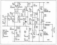
In a paper (by John Ellis P.hd), he proposed PLIL (Phase Lead Input Lag) method as an alternative method to stabilize an amp without Miller cap.
Phase lead = C4
Input lag = R4+C2
These 2 must both be used together.
Notice also he put R3 and R12.
In Bob's amp, the RC network in differential is put between collectors of input differential, in John Ellis' it is put on bases of input differential.
Phase lead = C4
Input lag = R4+C2
These 2 must both be used together.
Notice also he put R3 and R12.
In Bob's amp, the RC network in differential is put between collectors of input differential, in John Ellis' it is put on bases of input differential.
Attachments
J Ellis schematic
Hi,
what is the purpose of r12?
or is it simply to balance the input conditions with r3?
Note r17, compensation for constant voltage as Iq of the ccs (tr9) varies. Same as D. Self discusses but much later.
Hi,
what is the purpose of r12?
or is it simply to balance the input conditions with r3?
Note r17, compensation for constant voltage as Iq of the ccs (tr9) varies. Same as D. Self discusses but much later.
Hi, Mikeks,
PLIL has 2 components that must be used together "PL"and "IL".
If you only use C4, you don't make "PLIL", just "phase lead" compensation. John Ellis found out that only using "PL" is not enough to make an amp stable.
"PL" can be accompanied by (smaller) miller cap to make an amp stabile, but here it is the miller cap that is tried to be eliminated.
So "PL" needs another accompany to make the amp stable, but what? J. Ellis suggest to use "IL" to accompany "PL". The overall bode plot result of PLIL looks nice, but each component value of PLIL needs to be calculated.
Attachments
lumanauw said:Hi, Mikeks,
PLIL has 2 components that must be used together "PL"and "IL".
If you only use C4, you don't make "PLIL", just "phase lead" compensation.
Exactly:
http://www.diyaudio.com/forums/showthread.php?s=&postid=1047674&highlight=#post1047674
http://www.diyaudio.com/forums/showthread.php?postid=1117636#post1117636
- Home
- Amplifiers
- Solid State
- Bob Cordell Interview: Negative Feedback