😵 Is this typical? I sure hope my hearing will keep better. I'm 26 and can hear to 19.5 kHz, but quite attenuated beyond 17 kHz. I go to loud clubs but not for long periods and I take N-acetylcysteine.lumanauw said:I hear this from a friend. Age 50's, max hearable frequency about 13khz. Age 60's, max hearable frequency about 9khz (or 5khz?)
Sorry to be offtopic, but I didn't start it 😛
Hi, Nixie,
Carefull when clubbing 😀 When you get excited, usually you look for speaker and put your ears in 120dB source. Must be dangerous for your long term hearing 😀.
This hearing degradation is for all people. If I get that age too, I will suffer the same thing too 😀
Carefull when clubbing 😀 When you get excited, usually you look for speaker and put your ears in 120dB source. Must be dangerous for your long term hearing 😀.
This hearing degradation is for all people. If I get that age too, I will suffer the same thing too 😀
The problem is custom ear-mold earplugs are expensive. I'm sure if the price came down 10x the people would wear them.
G.Kleinschmidt said:
Ummm, I think that you need to read my post again. I didn't say one thing or another about the significance of "non-linear parallel impedance of several megohms". I was simply pointing out the fact the 67k is hardly any loading at all. At 20kHz, the loading of even a small miller compensation capacitor will be much, much greater, and it won't make the non-linearities, regardless of their significance, go away.
Well I think that it would not. 67k is totally insignificant, especially when any frequency compensation begins to load the VAS.
The only thing that light resistive loading of a VAS such as this may do is to prevent the open-loop gain from reaching astronomical levels at very low frequencies. That can, in some situations, despite actually worsening low frequency THD, improve the amplifiers overall low frequency THD+N performance.
But not for reasons that anyone here has cited thus far.
Hi Glen,
Here are a couple of points to keep in mind.
Although it is hard to make generalizations, a typical Miller compensation capacitor in a conventional amplifier might be on the order of 150 pF or less (the amplifier I have in mind has a closed loop bandwidth of only 200 kHz). The impedance of this 150 pF capacitor at 20 kHz is about 55 k, so it is certainly not much higher than a 67 k resistor.
Your purpose in putting the 67 k resistor there is interesting. It doesn't appear to be enough loading to increase the open loop bandwidth by a lot, certainly not enough to push it out to anywhere near 20 kHz (assuming you are using typical Miller compensation).
What exactly do you mean by in some situations, despite actually increasing LF THD, improve the amplifier's overall THD+N performance, and what are those reasons that no one here has cited so far?
Thanks,
Bob
Hi,
you lot are beginning to confuse me again.
The loading on the VAS stage due to the Miller compensation cap seems to be causing a loss of gain that increases with frequency.
But, where is all that current sinking to?
Can I pose another question?
Can one think of the comp cap as bypassing the signal around the VAS stage rather than through it? (a bit like an inverting opamp).
If this were the case then I can see a route for the LTP current sinking to the third stage.
That is the downfall of the comp cap, excessive loading of the LTP.
Or is my confusion total?
AndrewT said:Hi,
you lot are beginning to confuse me again.
The loading on the VAS stage due to the Miller compensation cap seems to be causing a loss of gain that increases with frequency.
But, where is all that current sinking to?
Can I pose another question?
Can one think of the comp cap as bypassing the signal around the VAS stage rather than through it? (a bit like an inverting opamp).
If this were the case then I can see a route for the LTP current sinking to the third stage.
That is the downfall of the comp cap, excessive loading of the LTP.
Or is my confusion total?
Hi Andrew,
The answer to your question lies in the basics of how Miller Effect compensation works. Miller compensation, in its simplest form, consists of a small capacitor connected from collector to base of the VAS CE stage. It forms a feedback loop around the VAS stage. Indeed, in the extreme case, it makes the VAS stage into an integrator. It does not roll off the VAS stage by dumping to ground greater and greater signal current as frequency increases (as would simple shunt compensation), but rather acts by working against the current being fed to the base of the VAS by the input stage.
If the net transconductance of the input stage is gm, and the impedance of the Miller compensation capacitor is Xc at a given frequency, then, in an ideal simplified situation, the gain of the input stage plus VAS at that frequency would be gm*Xc. This number will correspond to the open loop gain of the amplifier. The OLG will be approximately this amount as long as the miller capacitor is dominating the amount of gain. Put another way, this approximation will hold as long as the gain it calls for is less than the DC open loop gain of the amplifier. Keep in mind this is just handy back-of-the-envelope stuff. Think of the base of the VAS as the virtual ground inverting input of an operational amplifier that does not have a huge amount of gain.
Here is a simple example. Assume your input differential pair has 1 mA running in each transistor, and each is degenerated by 250 ohms. Assume we are using just a single-ended output from the diffamp to the VAS. Net transconductance of the input stage will be slightly less than 2 mmho. Assume we are at 20 kHz and we have a 70 pF Miller capacitor. Its reactance at 20 kHz is about 100k. OLG is then 2 mmho * 100k = 200. If the closed loop gain of the amplifier is 20:1, then the NFB factor is about 200/20 = 10, which is 20 dB of NFB at 20 khz. This amplifier will have a closed loop bandwidth of about 200 khz.
Cheers,
Bob
Bob Cordell said:
Hi Andrew,
The answer to your question lies in the basics of how Miller Effect compensation works. Miller compensation, in its simplest form, consists of a small capacitor connected from collector to base of the VAS CE stage. It forms a feedback loop around the VAS stage. Indeed, in the extreme case, it makes the VAS stage into an integrator. It does not roll off the VAS stage by dumping to ground greater and greater signal current as frequency increases (as would simple shunt compensation), but rather acts by working against the current being fed to the base of the VAS by the input stage.
If the net transconductance of the input stage is gm, and the impedance of the Miller compensation capacitor is Xc at a given frequency, then, in an ideal simplified situation, the gain of the input stage plus VAS at that frequency would be gm*Xc. This number will correspond to the open loop gain of the amplifier. The OLG will be approximately this amount as long as the miller capacitor is dominating the amount of gain. Put another way, this approximation will hold as long as the gain it calls for is less than the DC open loop gain of the amplifier. Keep in mind this is just handy back-of-the-envelope stuff. Think of the base of the VAS as the virtual ground inverting input of an operational amplifier that does not have a huge amount of gain.
Here is a simple example. Assume your input differential pair has 1 mA running in each transistor, and each is degenerated by 250 ohms. Assume we are using just a single-ended output from the diffamp to the VAS. Net transconductance of the input stage will be slightly less than 2 mmho. Assume we are at 20 kHz and we have a 70 pF Miller capacitor. Its reactance at 20 kHz is about 100k. OLG is then 2 mmho * 100k = 200. If the closed loop gain of the amplifier is 20:1, then the NFB factor is about 200/20 = 10, which is 20 dB of NFB at 20 khz. This amplifier will have a closed loop bandwidth of about 200 khz.
Cheers,
Bob
Amazing what you can do on the back of an envelope...!
Jan Didden
powerbecker said:Also if one like to use a opamp one cannot alter its circuit!
Which, perhaps, is why discrete design still thrives nearly 60 years after the invention of the op amp.
Bob Cordell said:Although it is hard to make generalizations, a typical Miller compensation capacitor in a conventional amplifier might be on the order of 150 pF or less (the amplifier I have in mind has a closed loop bandwidth of only 200 kHz). The impedance of this 150 pF capacitor at 20 kHz is about 55 k, so it is certainly not much higher than a 67 k resistor. Your purpose in putting the 67 k resistor there is interesting.
OK. I did not make my point very succinctly, but I did clarify it a bit in a later post. Also, please note that I am NOT actually advocating loading the VAS with a resistor, I’m arguing against the claims made for it.
One of the claims that has been made here is that loading the VAS with a resistor increases the bandwidth and linearity of the VAS and results in an “overall lowering in THD”. 67k was a value proposed by somebody else. Now I would interpret the claim of an “overall lowering in THD” to mean less distortion from 20Hz to 20kHz. If a resistor loading a VAS really did give a measurable and worthwhile reduction of THD at 20kHz, then it must, at the very least, be of a value that significantly impacts upon the operation of the circuit at frequencies well beyond 20kHz.
A value such as 67k or 50k simply does not. The impedance of a typical compensation capacitor at 20kHz is not much greater, but at the harmonic frequencies of 20kHz it definitely is. The role of such a resistor is therefore diminished.
It doesn't appear to be enough loading to increase the open loop bandwidth by a lot, certainly not enough to push it out to anywhere near 20 kHz (assuming you are using typical Miller compensation).
I agree entirely.
What exactly do you mean by in some situations, despite actually increasing LF THD, improve the amplifier's overall THD+N performance, and what are those reasons that no one here has cited so far?
OK. Firstly that isn't exactly what I said. I said overall low frequency THD+N performance. If you have an amplifier design with a very high input impedance (say 500k-1M) buffer for the output stage loading the VAS, the voltage gain of the VAS can become extremely large. Especially so if the VAS is a BJT current sunk with a reasonable bias current (say 5-10mA). This can quite easily produce a VAS with a low frequency voltage gain of 100dB unless heavily emitter degenerated. Suppose that a VAS such as this is preceded by a BJT differential amplifier with a voltage gain of 50. We now have a low frequency open loop gain in the vicinity of 130dB.
Unless running a very high closed loop gain, for stability such an amplifier would require dominant pole frequency compensation with a very low corner frequency. Maybe even as low as 10Hz. Due to the very high low frequency open loop gain, this amplifier may very well produce diminishingly low low-frequency THD, but it is very difficult to have both astronomical open loop gain and very low noise. A THD+N Vs Frequency plot for such an amplifier may not only show a typical gradual THD+N rise with increasing frequency from mid-band to 20kHz as the open-loop gain inevitably diminishes, but also the other way round – as frequency is decreased from mid-band to 20Hz, due to an excessive rise in low frequency open-loop gain which pushes the feedback error signal into the noise floor of the differential input amplifier.
Limiting the low frequency gain of the VAS with light resistive loading and re-compensating to suit can alleviate this problem.
Cheers,
Glen
Hi, Mr. Cordell,
In your mosfet amp, you dont use miller cap (B-C cap in Q10-Q11 or in Q14-Q15).
The only small caps on the front end is C3 and C4.
What is the reason you dont use Miller cap?
In your mosfet amp, you dont use miller cap (B-C cap in Q10-Q11 or in Q14-Q15).
The only small caps on the front end is C3 and C4.
What is the reason you dont use Miller cap?
Bob Cordell said:
Hi Glen,
Here are a couple of points to keep in mind.
Although it is hard to make generalizations, a typical Miller compensation capacitor in a conventional amplifier might be on the order of 150 pF or less (the amplifier I have in mind has a closed loop bandwidth of only 200 kHz). The impedance of this 150 pF capacitor at 20 kHz is about 55 k, so it is certainly not much higher than a 67 k resistor.
Your purpose in putting the 67 k resistor there is interesting. It doesn't appear to be enough loading to increase the open loop bandwidth by a lot, certainly not enough to push it out to anywhere near 20 kHz (assuming you are using typical Miller compensation).
What exactly do you mean by in some situations, despite actually increasing LF THD, improve the amplifier's overall THD+N performance, and what are those reasons that no one here has cited so far?
Thanks,
Bob
Bob,
I think there is some confusion of who said what on that 67k resistor load on the Vas. What I said was:
"The reasoning is as follows. The increase in high order harmonics with feedback happens because of the non-linearities in the forward path. The stronger the non-linearities, the more complex and higher-order the harmonics. Also, the stronger the feedback, the more complex and higher order the harmonics. You lose both ways.
So if we have less non-linearity to begin with [because the parallel resistor decreases Vas load modulation], and less feedback also [because of the lower loop gain resulting from the parallel load], even if the total RMS sum of the harmonics is the same, I 'think' that the thd spectrum will be more benign. You win both ways. What do you think?"
Reading your posts above, it seems that the 67k was not a good value for this particular discussion. But still, what do you think about the principle as quoted above?
Jan Didden
G.Kleinschmidt said:
That's a common misconception. A typical frequency compensated power amplifier may have an open loop crossover frequency in the vicinity of 1 MHz or more. When you consider just how much the miller compensation capacitor will be loading that VAS at those frequencies (not to mention the decreasing input impedence of the output driver stage), a 50k load resistor hardly makes a difference at all. As far as distortion is concerned, the only significant thing such a resistor will do is to increase the low frequency THD due to limiting the open loop gain, making not only the VAS work harder, but the preceding stage(s) as well.
Glen, we are not really in disagreement here, and I'm not under a misconception. In fact, the application of the resistor does tend to increase open loop bandwidth, but it is a matter of degree. In many cases, like yours, the amount of increase is not very much. In other cases, people who are believers in high open loop bandwidth sometimes do use the resistor to increase the open loop bandwidth by limiting the LF gain of the VAS. I was perhaps wrongly assuming that your use of the 67 k resistor was for the purpose of increasing open loop bandwidth. We also agree that the presence of the shunt resistor increases LF distortion and makes the VAS and input stage work harder. This is an assertion I made many posts ago.
Cheers,
Bob
G.Kleinschmidt said:
OK, I should have expressed my point a bit better. At 20kHz the VAS will be working much harder to drive the compensation capacitor at the harmonic frequencies of 20kHz, than into a 67k load resistor.
As far as high frequency THD is concerned, you have to consider the VAS performance several octaves above the audio frequency range.
At the fifth harmonic of 20kHz, the 68pF cap has an impedence of about 23k.
Unless you are using test signals at frequencies above 20 kHz, the compensation capacitor loading on the VAS does not matter in regard to making the VAS work harder to drive the capacitor, because it is not driving the capacitor at any frequencies above 20 kHz (other than with very low-level distortion harmonics). I think you are confused here.
Cheers,
Bob
G.Kleinschmidt said:
OK. I did not make my point very succinctly, but I did clarify it a bit in a later post. Also, please note that I am NOT actually advocating loading the VAS with a resistor, I’m arguing against the claims made for it.
One of the claims that has been made here is that loading the VAS with a resistor increases the bandwidth and linearity of the VAS and results in an “overall lowering in THD”. 67k was a value proposed by somebody else. Now I would interpret the claim of an “overall lowering in THD” to mean less distortion from 20Hz to 20kHz. If a resistor loading a VAS really did give a measurable and worthwhile reduction of THD at 20kHz, then it must, at the very least, be of a value that significantly impacts upon the operation of the circuit at frequencies well beyond 20kHz.
A value such as 67k or 50k simply does not. The impedance of a typical compensation capacitor at 20kHz is not much greater, but at the harmonic frequencies of 20kHz it definitely is. The role of such a resistor is therefore diminished.
I agree entirely.
OK. Firstly that isn't exactly what I said. I said overall low frequency THD+N performance. If you have an amplifier design with a very high input impedance (say 500k-1M) buffer for the output stage loading the VAS, the voltage gain of the VAS can become extremely large. Especially so if the VAS is a BJT current sunk with a reasonable bias current (say 5-10mA). This can quite easily produce a VAS with a low frequency voltage gain of 100dB unless heavily emitter degenerated. Suppose that a VAS such as this is preceded by a BJT differential amplifier with a voltage gain of 50. We now have a low frequency open loop gain in the vicinity of 130dB.
Unless running a very high closed loop gain, for stability such an amplifier would require dominant pole frequency compensation with a very low corner frequency. Maybe even as low as 10Hz. Due to the very high low frequency open loop gain, this amplifier may very well produce diminishingly low low-frequency THD, but it is very difficult to have both astronomical open loop gain and very low noise. A THD+N Vs Frequency plot for such an amplifier may not only show a typical gradual THD+N rise with increasing frequency from mid-band to 20kHz as the open-loop gain inevitably diminishes, but also the other way round – as frequency is decreased from mid-band to 20Hz, due to an excessive rise in low frequency open-loop gain which pushes the feedback error signal into the noise floor of the differential input amplifier.
Limiting the low frequency gain of the VAS with light resistive loading and re-compensating to suit can alleviate this problem.
Cheers,
Glen
Hi Glen,
I agree, a lightly-loaded VAS can have a very high gain for that stage. And yes, the preceding differential pair can also have a very high gain if it is loaded with a current mirror and the VAS is a Darlinton arrangement. An open loop gain at dc of 130+ dB in such an arrangement is certainly possible. My MOSFET power amplifier with error correction is in that category. And it is also true that the open loop bandwidth in such a case can be down in Hz range. For example, with straight 6 dB/octave rolloff, an amplifier with a 1 MHz gain crossover and 126 dB of OLG and 26 dB of CLG will have 100 dB of NFB at d.c. This will result in an open loop bandwidth of 10 Hz.
Where I disagree is that this large amount of OLG will cause an increase in noise. The noise in a properly designed amplifier will be dependent on the input referred noise of the input stage, regardless of the amount of open loop gain that follows. This is simple feedback theory as applied to noise analysis. Indeed, you WANT the input stage to have enough voltage gain so that the effective contribution of noise by the VAS is insignificant. My MOSFET amplifier exhibited extremely low noise, showing that your concern about noise exacerbated by lots of OLG is no a problem. I use an NPD5564 input dual FET, and the amplifier clocks in at a few nV per root Hz in the noise department.
Also, what some people fail to understand is that "low open loop bandwidth" does not in any way mean that the amplifier is "slow". The low open loop bandwidth happens merely as a result of large dc gain in conjuction with a 6 dB/octave compensation rolloff. Such amplifiers do not tend to have a larger Miller compensation capacitor than others with the same gain crossover frequency. The gain crossover frequency is what counts.
Cheers,
Bob
lumanauw said:Mr. Cordell,
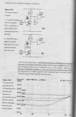
In Doug Self book, he mentioned a method to make linear OL response. The method is to put resistor about 220k in the place of miller cap (B-C of VAS). In the graph, 220k gives flat OL response.
What is your opinion about this method?
Yes, this method is essentially what I would use if I wanted wide open-loop bandwidth; I would establish it by feedback around the VAS, rather than loading the VAS. This avoids the difficulty of imposing a heavier load on the VAS. But, of course, the resistor must be a.c. coupled in the example he shows, to allow proper biasing. Also, this approach to achieving wide open loop bandwidth still imposes larger signal excursions across the full frequency band on the input stage, as compared with a design where the VAS is allowed to have higher gain at low frequencies.
Cheers,
Bob
lumanauw said:Hi, Mr. Cordell,
In your mosfet amp, you dont use miller cap (B-C cap in Q10-Q11 or in Q14-Q15).
The only small caps on the front end is C3 and C4.
What is the reason you dont use Miller cap?
There are three reasons why I do not use Miller compensation in my amplifier.
When you have a complementary VAS, as in my design, I don't like the idea of having two Miller capacitors feeding back, one to the p vas base and one to the n vas base. I worry, perhaps needlessly, that they will "fight" each other (you have essentially built two stages, each with a low output impedance at high frequency resulting from the shunt feedback of the capacitor, and these two stages are now connected in parallel).
Miller compensation leads to sub-optimal slew rate. The kind of compensation I use, which is a form of input FB compensation that acts like Miller compensation, but goes all the way back to the input, alleviates the slew rate limitation imposed by Miller compensation. That is why my 50 watt amplifier easily achieves a linear slew rate of over 300 V/us. The FB loop formed by this input compensation is compensated by the series RC circuit placed across the differential output of the input stage. That loop has a gain crossover somewhere between 10 and 20 MHz.
Finally, Miller compensation impairs high-frequency PSRR, since one end of the Miller capacitor must essentially track the supply rail. In my circuit, both ends of the equivalent capacitor are at signal nodes. In a sense, this is more symmetrical.
I frequently discuss amplifiers in terms of Miller compensation because it is conceptually simple and it is used widely. But it is definitely not the best.
Cheers,
Bob
Bob Cordell said:
Hi Pete, I'm sorry I took so long to get back to answer your question. The assumption is that we are applying your two-tone test to an open-loop amplifier that has been compensated for a given amount of open-loop gain at 20 kHz. The question I think you are positing, is, if at a given output voltage level, the presence or absence of the VAS load resistor makes a difference in the two-tone LF IM. Is that right? The presumption is that the net shunt resistance we apply causes the open loop bandwidth to increase. This is the same as saying that the shunt resistor causes the LF gain to be reduced to approximately the same level as the gain will be at the new open loop corner frequency.
If the output stage is a triple, with a high input impedance of about 500k, the gain even at 100 Hz will still largely be controlled by the necessary Miller compensation capacitor when there is no load resistor (especially if the input stage is loaded with a current mirror). When we add the load resistor, the p-p current of the VAS will have to increase from a very small amount necessary to drive the 500K load, to a larger amount necessary to drive the shunt resistor. If the shunt resistor is 50 k, this current will have to increase by a factor of 10. This still may not cause much distortion, but it is, nevertheless, going to be an increase in the distortion caused by nonlinearities in the VAS. Suppose the VAS is biased at 10 mA, and we want 100v p-p. The p-p current to drive the 50 k resistor will be about 2 mA, so the VAS collector current is changing by 20% to achieve this swing.
So, yes, the 100 Hz & 110 HZ twin tone IM will tend to increase when the load resistor is applied.
Cheers,
Bob
I had my own answer in mind, which is that it depends based on your earlier statement that did not have all this detail. OK, so there were some assumptions behind your earlier statement. I'm not sure that I agree, but I'd have to simulate or test to show my view and I just don't have the time. Interesting to read your view anyway, thanks.
Pete B.
Bob Cordell said:
Where I disagree is that this large amount of OLG will cause an increase in noise. The noise in a properly designed amplifier will be dependent on the input referred noise of the input stage, regardless of the amount of open loop gain that follows. This is simple feedback theory as applied to noise analysis. Indeed, you WANT the input stage to have enough voltage gain so that the effective contribution of noise by the VAS is insignificant. My MOSFET amplifier exhibited extremely low noise, showing that your concern about noise exacerbated by lots of OLG is no a problem. I use an NPD5564 input dual FET, and the amplifier clocks in at a few nV per root Hz in the noise department.
Cheers,
Bob
OK, but I do not believe that just because you achieved good results with a very low noise jfet input stage and reasonably high LF open loop gain that a relationship between OLG and noise simply isn’t a design problem. What if your OLG was 30dB higher and you input stage was composed of a pair of BC850's? Have you tried that? Perhaps the hypothetical numbers I provided in my example were not extreme enough. I currently have an experimental all-BJT pre amplifier design on my bench. It consists to two cascaded differential amplifiers each with a gain of ~70 followed by a VAS with extremely light loading (>1M). OLG is in the vicinity of 180db. Tested open loop, with the DC operating point is set with a servo and the individual stages shielded to prevent oscillation (not an easy task), the circuit is a noise generator - 10V peak of noise in fact, which is the clipping / saturation level. Even with the OL bandwidth subsequently rolled-off for frequency compensation for a closed loop gain of 20dB, there is still plenty of noise on the output with the input terminated.
Closing the loop does reduce the noise for sure, but it is next to pointless to raise the OLG to such an extent that the amplitude of the feedback error signal for the closed loop (which is, after all, the actual signal that the input differential amplifier sees) is below or well below the noise floor of the input differential amplifier.
When this point is reached, increasing the OLG for more negative feedback only increases the noise amplification, which it then has to act against.
Cheers,
Glen
Bob Cordell said:
Unless you are using test signals at frequencies above 20 kHz, the compensation capacitor loading on the VAS does not matter in regard to making the VAS work harder to drive the capacitor, because it is not driving the capacitor at any frequencies above 20 kHz (other than with very low-level distortion harmonics). I think you are confused here.
Cheers,
Bob
I think that you completely missed my point. A claim that has been made here for light resistive loading of the VAS is that can give an overall lowering of THD. I disagree. The value posited was 67k, in parallel with a 68pF compensation capacitor connected from the VAS collector to ground.
The THD generated when operating at 20kHz is governed by the performance of the amplifier at the harmonic frequencies of 20kHz, right? At the harmonic frequencies of 20kHz the impedance of the 68pF capacitor makes the role of the 67k resistor practically negligible.
Cheers,
Glen
- Home
- Amplifiers
- Solid State
- Bob Cordell Interview: Negative Feedback