To B. Cordell
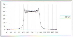
Here is the spectrum of the impulse I mentionned to you a few posts above.
This impulse is a linear swept sine from 100hz to 200 hz in 1 second.
You can see that this signal has a selective spectrum. If a system is excited with this impulse and if the amplitude is increased, we can analyze the spectrum of the output outside the band and get there components generated by non linearities in a transient way.
The ratio of out of band energy to in band or total input energy is a figure that is perhaps better correlated to aural impression than THD.
What do you think?
JPV
Attachments
Re: Re: Re: CFB clamp
Hi Edmond,
You are correct if:
1) the base-collector capacitance of the pre-drivers is as big and as bad as that of the diode used for the Baker clamp;
2) you have an architecture where the base-collector capacitance of the pre-drivers is able to create a nonlinear capacitive load in the conventional way.
Cheers,
Bob
Edmond Stuart said:
Hi Bob,
This seems a very clever idea, but as long as the VAS output is also loaded with the nonlinear base-collector capacitance of the pre-drivers, it is not a big deal.
Cheers.

Hi Edmond,
You are correct if:
1) the base-collector capacitance of the pre-drivers is as big and as bad as that of the diode used for the Baker clamp;
2) you have an architecture where the base-collector capacitance of the pre-drivers is able to create a nonlinear capacitive load in the conventional way.
Cheers,
Bob
Re: Re: Re: Re: CFB clamp
Hi Bob,
1. The capacitance of a 1N914, for example, is 2.5pF at Vd=0V
I don't know of any tranny that has a lower Cob value at Vcb = 0V
(btw, 2N5551: Cjc=5pF, 2N5401: Cjc = 17pF)
2. Normally, we do have such architecture. Take your EC amp for example: the bases of Q20/Q21 are connected to the VAS output, while collectors are tied to the supply rails. So Vce and thus Cob is modulated by the full swing of the output signal. In other words, the VAS output is loaded with the nonlinear capacitances of the pre-drivers.
Or are we on cross purposes a bit here? If that's the case, a schematic of your floating clamp would be really helpful.
Cheers, Edmond.
Bob Cordell said:
Hi Edmond,
You are correct if:
1) the base-collector capacitance of the pre-drivers is as big and as bad as that of the diode used for the Baker clamp;
2) you have an architecture where the base-collector capacitance of the pre-drivers is able to create a nonlinear capacitive load in the conventional way.
Cheers,
Bob
Hi Bob,
1. The capacitance of a 1N914, for example, is 2.5pF at Vd=0V
I don't know of any tranny that has a lower Cob value at Vcb = 0V
(btw, 2N5551: Cjc=5pF, 2N5401: Cjc = 17pF)
2. Normally, we do have such architecture. Take your EC amp for example: the bases of Q20/Q21 are connected to the VAS output, while collectors are tied to the supply rails. So Vce and thus Cob is modulated by the full swing of the output signal. In other words, the VAS output is loaded with the nonlinear capacitances of the pre-drivers.
Or are we on cross purposes a bit here? If that's the case, a schematic of your floating clamp would be really helpful.
Cheers, Edmond.
Talking about distortion measurement related to feedback. What happens when a multitude of test tones are fed into an amp? There has been a lot of discussion about 2 tone HF intermodulation tests. But what happens if we inject 5 or 6 or even more tone pairs into an amp and look at the harmonics produced. I ask this because this type of test would be more repreentative of a real music signal. I seem to recall that someome (Blumenthal?) proposed something like this but using some comb filter technique.
It would be intersting to compare zero f/back, tube, current feedback and voltage feedback amps in this way.
It would be intersting to compare zero f/back, tube, current feedback and voltage feedback amps in this way.
You get more intermodulation and harmonic distortion products mixed together, that are more difficult to distinguish. In case of very low distortion design, you would see nothing special.
Audio Precision, dScope, Neutrik all do this kind of thing. You do a multitone followed by an FFT. If you chose your freq very carefully, you can identify the FFT bins with the harmonic products, the IM products, noise and xtalk, all in one measurement. The Neutrik RT-2M does that in half a second...
It's a bit involved, but if you want to try yourself, these are the ISO31 frequencies you should use:
17.575
23.450
29.300
41.025
52.725
64.450
82.025
99.600
123.050
158.200
199.225
252.000
316.500
398.500
498.000
632.750
802.750
1,002.000
1,248.000
1,599.500
1,998.000
2,502.500
3,152.500
4,002.500
4,997.500
6,352.500
7,997.500
10,002.500
12,497.500
16,002.500
19,997.500
Jan Didden
Sometimes it is difficult to measure better object by worse instrumentation. SYS2722 meets the current demands, the AP1 does not.
PMA said:Sometimes it is difficult to measure better object by worse instrumentation. SYS2722 meets the current demands, the AP1 does not.
That is true, but I would suggest that when all your distortion products, however measured, are below 100dB, the measurements stop to be of relevance for audibility. They probably are already way before that, but let's take a safety margin.
The measurement industry dutyfully follows all colloraries of the Peter Principle. If the available measurement resolution can be improved, someone will find a reason why it is absolutely necessary to use it 😉
Jan Didden
janneman said:
That is true, but I would suggest that when all your distortion products, however measured, are below 100dB, the measurements stop to be of relevance for audibility.
Yes, as far as we measure unimportant parameters and graphs. These methods are averaging, do not reveal unperiodic phenomena. That is why they do correlate poorly with what we hear.
PMA said:
Yes, as far as we measure unimportant parameters and graphs. These methods are averaging, do not reveal unperiodic phenomena. That is why they do correlate poorly with what we hear.
Whoa! Not so fast 😉 .
We were takling about stimulating an amp with a spectrum of up to 31 tones. That's not averaging etc etc. The idea was to get a bit closer to real music with the test signal. That's one issue. The other was that you said that an AP S1, which routinely measures up to -120dB non-linear components, was not adequate for the best equipment out there, and we really should buy a 2722 at, what is it, 50k$ a shot?
That may be true, but we always bragg (!) how irrelevant our measurements are for audibility. Are you saying that if we can look beyond -120dB that *would* be relevant for audibility?
Jan Didden
Re: Re: Re: Re: Re: CFB clamp
Hi Edmond,
You're right about the 1N914 or 1N4148 diode capacitance in respect to what we are likely to get for Ccb for many pre-driver transistors connected in a source follower arrangement. The fact that boosted supplies mitigate this a bit by providing higher collector-base reverse bias on the pre-driver mitigates this a bit, but not as much as we would like.
Unfortunately, the 1N4148 has only a 100V breakdown, and leakage may begin to increase beyond about 75V. This is not enough for the nearly rail-to-rail reverse voltage that a conventional Baker clamp diode can see in a larger power amplifier. I may not have looked hard enough, but I haven't seen many small-signal diodes that are rated at 200V with really small capacitance. Let me know if you have one you like.
The Flying Baker Clamp allows us to separate the issues of clamping diode characteristics from voltage rating and non-linear capacitance issues. Nevertheless, I agree with you that I may be guilding the lilly by using such an approach in many applications where other sources of non-linear junction capacitance may dominate.
You are right about my old EC amp. I was not worrying very much in that design about the non-linear junction capacitance loading on the VAs output node from the coscode VAS output transistors, the pre-driver transistors, or the Baker Clamp diodes. I guess if you are looking for only 0.0006% THD-20 these considerations are not a dominant problem 🙂.
Cheers,
Bob
Edmond Stuart said:
Hi Bob,
1. The capacitance of a 1N914, for example, is 2.5pF at Vd=0V
I don't know of any tranny that has a lower Cob value at Vcb = 0V
(btw, 2N5551: Cjc=5pF, 2N5401: Cjc = 17pF)
2. Normally, we do have such architecture. Take your EC amp for example: the bases of Q20/Q21 are connected to the VAS output, while collectors are tied to the supply rails. So Vce and thus Cob is modulated by the full swing of the output signal. In other words, the VAS output is loaded with the nonlinear capacitances of the pre-drivers.
Or are we on cross purposes a bit here? If that's the case, a schematic of your floating clamp would be really helpful.
Cheers, Edmond.
Hi Edmond,
You're right about the 1N914 or 1N4148 diode capacitance in respect to what we are likely to get for Ccb for many pre-driver transistors connected in a source follower arrangement. The fact that boosted supplies mitigate this a bit by providing higher collector-base reverse bias on the pre-driver mitigates this a bit, but not as much as we would like.
Unfortunately, the 1N4148 has only a 100V breakdown, and leakage may begin to increase beyond about 75V. This is not enough for the nearly rail-to-rail reverse voltage that a conventional Baker clamp diode can see in a larger power amplifier. I may not have looked hard enough, but I haven't seen many small-signal diodes that are rated at 200V with really small capacitance. Let me know if you have one you like.
The Flying Baker Clamp allows us to separate the issues of clamping diode characteristics from voltage rating and non-linear capacitance issues. Nevertheless, I agree with you that I may be guilding the lilly by using such an approach in many applications where other sources of non-linear junction capacitance may dominate.
You are right about my old EC amp. I was not worrying very much in that design about the non-linear junction capacitance loading on the VAs output node from the coscode VAS output transistors, the pre-driver transistors, or the Baker Clamp diodes. I guess if you are looking for only 0.0006% THD-20 these considerations are not a dominant problem 🙂.
Cheers,
Bob
Re: Re: Re: Re: Re: Re: CFB clamp
Used in PGP: http://www.onsemi.com/pub_link/Collateral/BAS21HT1-D.PDF
It's basically a high voltage 1N914.
Bob Cordell said:
I may not have looked hard enough, but I haven't seen many small-signal diodes that are rated at 200V with really small capacitance. Let me know if you have one you like.
Used in PGP: http://www.onsemi.com/pub_link/Collateral/BAS21HT1-D.PDF
It's basically a high voltage 1N914.
Re: Re: Re: Re: Re: Re: Re: CFB clamp
Thanks! I see it's rated at 5 pF max at 0V. That's pretty good, although I wish the data sheet would show a plot of the typical Cj vs Vr. The 1N4148 is rated at 4 pF max at 0V, but the plot of the typical comes in under that. It's always nice to see what the actual typical is, because some manufacturers can get sloppier than others in specifying the max.
Cheers,
Bob
syn08 said:
Used in PGP: http://www.onsemi.com/pub_link/Collateral/BAS21HT1-D.PDF
It's basically a high voltage 1N914.
Thanks! I see it's rated at 5 pF max at 0V. That's pretty good, although I wish the data sheet would show a plot of the typical Cj vs Vr. The 1N4148 is rated at 4 pF max at 0V, but the plot of the typical comes in under that. It's always nice to see what the actual typical is, because some manufacturers can get sloppier than others in specifying the max.
Cheers,
Bob
@Bob:
Check out Rohm's 1SS244, 200mA-DC, 220V-DC, 3pF-max@0V,1MHz (typ.: <1pF). And it's available in through-hole DO-34 or MELF (RLS245) form factors.
Rohm has quite extensive datasheets, compared to the usual stuff.
- Klaus
Check out Rohm's 1SS244, 200mA-DC, 220V-DC, 3pF-max@0V,1MHz (typ.: <1pF). And it's available in through-hole DO-34 or MELF (RLS245) form factors.
Rohm has quite extensive datasheets, compared to the usual stuff.
- Klaus
janneman said:Audio Precision, dScope, Neutrik all do this kind of thing. You do a multitone followed by an FFT. If you chose your freq very carefully, you can identify the FFT bins with the harmonic products, the IM products, noise and xtalk, all in one measurement. The Neutrik RT-2M does that in half a second...
It's a bit involved, but if you want to try yourself, these are the ISO31 frequencies you should use:
...
Jan Didden
Hi,
To get really good resolution in Spice, I make the lowest
frequency start on some easy multiple of the start/stop time.
I use 5 requencies like so:
1000
1778.279
3162.278
5623.413
10000
and set LTSpice stop/start/timestep at something like:
1.01/.01/.0000001
This provides 5 multitones that are equal logarithmically
spaced with very good resolution.
Mike
mfc said:
Hi,
To get really good resolution in Spice, I make the lowest
frequency start on some easy multiple of the start/stop time.
I use 5 requencies like so:
1000
1778.279
3162.278
5623.413
10000
and set LTSpice stop/start/timestep at something like:
1.01/.01/.0000001
This provides 5 multitones that are equal logarithmically
spaced with very good resolution.
Mike
Mike,
Thanks, 'll try it out. What kind of windowing do you use? All frequencies start with zero phase?
Jan Didden
KSTR said:@Bob:
Check out Rohm's 1SS244, 200mA-DC, 220V-DC, 3pF-max@0V,1MHz (typ.: <1pF). And it's available in through-hole DO-34 or MELF (RLS245) form factors.
Rohm has quite extensive datasheets, compared to the usual stuff.
- Klaus
Thanks, Klaus.
This looks like a very nice diode. One thing I particularly like is the Ct dispersion map, showing actual capacitance of numerous samples, fairly tightly clustered, and having an average value of 0.94 pF. This compares very favorably with the apparently conservative maximum rated value of 3 pF.
Thanks,
Bob
janneman said:
Mike,
Thanks, 'll try it out. What kind of windowing do you use? All frequencies start with zero phase?
Jan Didden
Hi,
I use Hahn and start everything from 0 degrees. The only
cautionary is to have several Gig of space available and
some patience with the time it takes.
Mike
mfc said:
Hi,
I use Hahn and start everything from 0 degrees. The only
cautionary is to have several Gig of space available and
some patience with the time it takes.
Mike
OK, I ran the multitone generator of the AP S1 software, and it came up with this:
waveform statistics:
Generating Component = 186 cycles of 1001.29395 Hz at 0 dB
Generating Component = 330 cycles of 1776.48926 Hz at 0 dB
Generating Component = 587 cycles of 3159.99756 Hz at 0 dB
Generating Component = 1045 cycles of 5625.54932 Hz at 0 dB
Generating Component = 1858 cycles of 10002.1729 Hz at 0 dB
Using sample rate of 44100 Hz
Calculating Peak and RMS with NO Oversampling.
1X Waveform Peak Value (in input units) = 4.76414
1X Waveform RMS Value (in input units) = 1.58114
1X Waveform Crest Factor = 3.01311
Calculating Peak and RMS with 8X peak oversampling 401 tap filter.
8X Waveform Peak Value (in input units) = 4.83429
8X Waveform RMS Value (in input units) = 1.58114
8X Waveform Crest Factor = 3.05748
Output waveform Headroom = 1 dB
Absolute output level = -14.6867 dBFS.
(corresponding to 1 Volt or 0 dB input file specification).
This is for a 1 sec test signal.
- Home
- Amplifiers
- Solid State
- Bob Cordell Interview: Negative Feedback