broken loop
Hi Jan,
If you don't mind I'll answer you tomorrow, because I'm in the middle of simulating 18 different topologies of the NFB-OPS and, at least equally important, I have to prepare diner.
Regards,
Edmond.
Hi Jan,
If you don't mind I'll answer you tomorrow, because I'm in the middle of simulating 18 different topologies of the NFB-OPS and, at least equally important, I have to prepare diner.
Regards,
Edmond.
Re: broken loop
After discussing this for 2 years, you think I will complain about 2 days? 😉
Jan Didden
Edmond Stuart said:Hi Jan,
If you don't mind I'll answer you tomorrow, because I'm in the middle of simulating 18 different topologies of the NFB-OPS and, at least equally important, I have to prepare diner.
Regards,
Edmond.
After discussing this for 2 years, you think I will complain about 2 days? 😉
Jan Didden
Re: Re: confusing symantics?
Hi Jan,
So you have troubles with where I was breaking the loop, right? But why? As long as we comply with a couple of rules (see below), we may break the loop anywhere without disturbing the operation of the circuit or even creating a different circuit. Looking at different loops will of course result in different figures. And of course these different figures have a different meaning as well. Nothing wrong with that, provided that we are talking about the same thing.
When I'm analyzing an amp I always look at every loop, in particular those with a high loop gain and/or with high unity-gain-loop-bandwidth, because they are the most potential trouble makers. In a traditional power amp, for example, these are the global NFB loop and the Miller compensation loop.
They both must have a sufficiently large phase margin in order to make the amp (as a whole) stable.
In case of HEC, I'm following exactly the same procedure: searching for the loop with the highest gain or BW. Also in this case it's that loop that tells us whether there are stability issues (opposed to low gain loops).
Now I hope that you will understand that I have no objections against other views per se, but only against views that ignore important aspect (read: stability issues).
Some side notes: Some people define the NFB factor as forward gain without FB divided by forward gain with FB. (in case of HEC this will yield a very low number). I never use this definition as it is complete meaningless. I always look at the gain and phase response of a loop, because these are the things that determine the stability.
Some rules for breaking a loop:
1. Always preserve the DC operating point
Observe the impedances at the point where the loop will be broken.
2. If Zi >> Zo, look at voltages. Gv = Vo/Vi
3. If Zi << Zo, look at currents. Gi = Io/Ii.
4. If Zi ~= Zo, look at current and voltages as well. Now the effective loop gain is: G = Gv || Gi = 1 / (1/Gv + 1/Gi ). This is the method of Middlebrook, btw.
Hope this will clarify the confusion and will lead to a 'unified' view on HEC.
Regards,
Edmond.
janneman said:Hi Edmond,
Possibly there is some miscommunication there. I also have this 'deja vu' feeling...
Anyway. The system response is determined by the combination of pos and neg feedback. This feedback is summed and send to the inverting input of the input summer. It seems to me logical that when you want to inspect the loop by breaking it, you would break it between the output of the feedback summer and the input of the input summer, because then you really break the (combined) feedback loop.
[snip]
... If you only break the nfb loop, you are no longer looking at the original circuit but at a completely different one. So this doesn't tell you anything about the original Hec circuit.
Jan Didden
Hi Jan,
So you have troubles with where I was breaking the loop, right? But why? As long as we comply with a couple of rules (see below), we may break the loop anywhere without disturbing the operation of the circuit or even creating a different circuit. Looking at different loops will of course result in different figures. And of course these different figures have a different meaning as well. Nothing wrong with that, provided that we are talking about the same thing.
When I'm analyzing an amp I always look at every loop, in particular those with a high loop gain and/or with high unity-gain-loop-bandwidth, because they are the most potential trouble makers. In a traditional power amp, for example, these are the global NFB loop and the Miller compensation loop.
They both must have a sufficiently large phase margin in order to make the amp (as a whole) stable.
In case of HEC, I'm following exactly the same procedure: searching for the loop with the highest gain or BW. Also in this case it's that loop that tells us whether there are stability issues (opposed to low gain loops).
Now I hope that you will understand that I have no objections against other views per se, but only against views that ignore important aspect (read: stability issues).
Some side notes: Some people define the NFB factor as forward gain without FB divided by forward gain with FB. (in case of HEC this will yield a very low number). I never use this definition as it is complete meaningless. I always look at the gain and phase response of a loop, because these are the things that determine the stability.
Some rules for breaking a loop:
1. Always preserve the DC operating point
Observe the impedances at the point where the loop will be broken.
2. If Zi >> Zo, look at voltages. Gv = Vo/Vi
3. If Zi << Zo, look at currents. Gi = Io/Ii.
4. If Zi ~= Zo, look at current and voltages as well. Now the effective loop gain is: G = Gv || Gi = 1 / (1/Gv + 1/Gi ). This is the method of Middlebrook, btw.
Hope this will clarify the confusion and will lead to a 'unified' view on HEC.
Regards,
Edmond.
Edmond Stuart said:If you don't mind I'll answer you tomorrow, because I'm in the middle of simulating 18 different topologies of the NFB-OPS and, at least equally important, I have to prepare diner.
Hi Edmond, would you like some french cheese made by Mr Askamp ?
Attachments

Hi Jan, sorry I am being a little slow. Not much time to reply this week.
If one defines "NFB on demand" as meaning that you don't apply force to the handlebars unless you see a deviation, then that is ok. But this is not an engineering description and it does not distinguish HEC from any other FB system. IOW, "view #3" is meaningless.
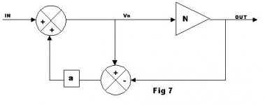
I think we need a diagram. Is A the "plant" (the gain block being corrected) or is it the HEC adjust block. My memory is vague. I've attached a redraw of the Hawksford block diagram.
In any case I think the way we are looking at feedback is different. One thing I like to do is consider the "plant" independently of the NFB loop. The plant is the N block. Suppose that Vin=Vn=Vout and N=1. This is like the condition where you can let go of the handlebars with no impact. Now imagine removing the N block. Suppose Vout changes slightly, what impact will this have on the input to the plant? This impact is like the "force" of the FB or the rotational force of your hands on the handlebars.
I hope this explains that the the term "NFB on demand" is not very apt. The NFB response to deviation (the NFB power if you will) is always present. This is true of all FB systems.janneman said:OK, I think I understand better your reasoning. Even if at the time where there is no deviation, and I take my hands of the handlebars, still, when there *would* be a deviation, I'll react to it. So, the fb, as a system attribute, is still there even if latent. Not sure where this leads, but I get your reasoning.
If one defines "NFB on demand" as meaning that you don't apply force to the handlebars unless you see a deviation, then that is ok. But this is not an engineering description and it does not distinguish HEC from any other FB system. IOW, "view #3" is meaningless.
I've done some more thinking about that Ve derivative. I would have thought that at a point where the fb would be infinite, the derivative of the feedback (factor) would be 0. Indeed, if you plot Ve for a range of A (see attachment) you find that at much higher A, the derivative asymptotes to 0. And, as noted, for A=1, the derivative = 1 as well.
Now if A becomes much higher that 1, we can expect the 'effective' fb to grow much higher as the nfb part of the combined loop starts to increase and dominate. That would jive with the derivative going to 0. But that would also indicate that the total system feedback at A=1 isn't infinite. Since the total system feedback is build up from a negative feedback part and a positive feedback part (giving an infinite gain block), those parts being exactly equal at A=1, this all seems to make sense.
I think we need a diagram. Is A the "plant" (the gain block being corrected) or is it the HEC adjust block. My memory is vague. I've attached a redraw of the Hawksford block diagram.
In any case I think the way we are looking at feedback is different. One thing I like to do is consider the "plant" independently of the NFB loop. The plant is the N block. Suppose that Vin=Vn=Vout and N=1. This is like the condition where you can let go of the handlebars with no impact. Now imagine removing the N block. Suppose Vout changes slightly, what impact will this have on the input to the plant? This impact is like the "force" of the FB or the rotational force of your hands on the handlebars.
Attachments

Re: Re: Re: confusing symantics?
Hi Edmond,
I believe that indeed the crux of our discussion is where to break the loop to find 'the' feedback factor (or loop gain or check stabilty or whatever).
I think we agree that to facilitate the analysis of a system with multiple parallel loops you transform it into a system with a single loop. You can then cut that loop anywhere you want (depending on, perhaps, where it is most convenient wrt i/o impedances).
Let's look at the two transformations discussed before.
I transfer the pos feedback point from the input of the forward block A to it's output, and divide it by A. I then get a single loop, going from Vout to Vin via the transfer function 1-1/A (assuming all summers are unity gain). I can then open that loop anywhere for analyses as you propose.
I believe it is important to realise that by doing this, you work both feedback loops into a single transfer function. That is why it is legal to then open the loop anywhere, because always you cut both the pos and the neg feedback loop at the same time. That means, that opening the loop this way and measuring, you can make statements about the original Hec system as such, beacuse it is *defined* by the combined fb loops.
You (and Brian) proposed to rework the Hec circuit by separating out the pos and neg feedback loop, and indeed I have used the same scheme to offer another look at Hec, as it clearly illustrates the embedded infinite gain block. In that scheme, the pos feedback loop would be a separate loop 'into itself' in front of the A plant, while the nfb loop would be a global loop from Vout to Vin. This is a valid alternate view of the circuit with an identical transfer function, and supports 'view #1'.
But when, in this last transformed circuit, you now open just one of those loops, either the pos or the neg fb loop, you don't open 'the' combined fb loop (which is the defining property the Hec system in the first place) but only one loop. You can of course do measurements now to inspect stability issues, but you cannot, in this situation, draw any conclusions about 'the' feedback factor, and 'the' Hec system as such.
Edmond, I think this is my main point. The two transformations (separating out the loops or combining them) as such are both perfectly legal. The difference becomes manifest when loops are being opened, and that also explains the difference in our measurements. Actually, the fact that we DO measure different properties is a clear indicator that the two reworked circuits are NOT equivalent *wrt opening up the loop(s)*. Since the combination of the feedback loops is a defining property of Hec, I believe opening the loop in my proposed transformation gives the correct results for the system.
You gave the example of a classical power amp where you have a global feedback loop as well as a Vas integrator loop. In that case, you can indeed cut either the global loop, or the Vas fb loop, and look at properties of the system. This is valid because the combination of the two loops as such is not the defining property of the power amp. The loops are independent. The combination of a global nfb loop and a Vas loop is not a defining property of a nfb power amp. For instance, you can open the Vas loop only, can change its properties (miller, TMC, whatever), leave it out completely or replace it with something different somewhere else in the circuit, and you would still have an nfb power amp. You cannot do that with Hec because when opening only one loop it would no longer be a Hec system: *the* defining property of Hec is the intertwined combined fb loops.
Jan Didden
Edmond Stuart said:
Hi Jan,
So you have troubles with where I was breaking the loop, right? But why? As long as we comply with a couple of rules (see below), we may break the loop anywhere without disturbing the operation of the circuit or even creating a different circuit. Looking at different loops will of course result in different figures. And of course these different figures have a different meaning as well. Nothing wrong with that, provided that we are talking about the same thing.
When I'm analyzing an amp I always look at every loop, in particular those with a high loop gain and/or with high unity-gain-loop-bandwidth, because they are the most potential trouble makers. In a traditional power amp, for example, these are the global NFB loop and the Miller compensation loop.
They both must have a sufficiently large phase margin in order to make the amp (as a whole) stable.
In case of HEC, I'm following exactly the same procedure: searching for the loop with the highest gain or BW. Also in this case it's that loop that tells us whether there are stability issues (opposed to low gain loops).
Now I hope that you will understand that I have no objections against other views per se, but only against views that ignore important aspect (read: stability issues).
Some side notes: Some people define the NFB factor as forward gain without FB divided by forward gain with FB. (in case of HEC this will yield a very low number). I never use this definition as it is complete meaningless. I always look at the gain and phase response of a loop, because these are the things that determine the stability.
Some rules for breaking a loop:
1. Always preserve the DC operating point
Observe the impedances at the point where the loop will be broken.
2. If Zi >> Zo, look at voltages. Gv = Vo/Vi
3. If Zi << Zo, look at currents. Gi = Io/Ii.
4. If Zi ~= Zo, look at current and voltages as well. Now the effective loop gain is: G = Gv || Gi = 1 / (1/Gv + 1/Gi ). This is the method of Middlebrook, btw.
Hope this will clarify the confusion and will lead to a 'unified' view on HEC.
Regards,
Edmond.
Hi Edmond,
I believe that indeed the crux of our discussion is where to break the loop to find 'the' feedback factor (or loop gain or check stabilty or whatever).
I think we agree that to facilitate the analysis of a system with multiple parallel loops you transform it into a system with a single loop. You can then cut that loop anywhere you want (depending on, perhaps, where it is most convenient wrt i/o impedances).
Let's look at the two transformations discussed before.
I transfer the pos feedback point from the input of the forward block A to it's output, and divide it by A. I then get a single loop, going from Vout to Vin via the transfer function 1-1/A (assuming all summers are unity gain). I can then open that loop anywhere for analyses as you propose.
I believe it is important to realise that by doing this, you work both feedback loops into a single transfer function. That is why it is legal to then open the loop anywhere, because always you cut both the pos and the neg feedback loop at the same time. That means, that opening the loop this way and measuring, you can make statements about the original Hec system as such, beacuse it is *defined* by the combined fb loops.
You (and Brian) proposed to rework the Hec circuit by separating out the pos and neg feedback loop, and indeed I have used the same scheme to offer another look at Hec, as it clearly illustrates the embedded infinite gain block. In that scheme, the pos feedback loop would be a separate loop 'into itself' in front of the A plant, while the nfb loop would be a global loop from Vout to Vin. This is a valid alternate view of the circuit with an identical transfer function, and supports 'view #1'.
But when, in this last transformed circuit, you now open just one of those loops, either the pos or the neg fb loop, you don't open 'the' combined fb loop (which is the defining property the Hec system in the first place) but only one loop. You can of course do measurements now to inspect stability issues, but you cannot, in this situation, draw any conclusions about 'the' feedback factor, and 'the' Hec system as such.
Edmond, I think this is my main point. The two transformations (separating out the loops or combining them) as such are both perfectly legal. The difference becomes manifest when loops are being opened, and that also explains the difference in our measurements. Actually, the fact that we DO measure different properties is a clear indicator that the two reworked circuits are NOT equivalent *wrt opening up the loop(s)*. Since the combination of the feedback loops is a defining property of Hec, I believe opening the loop in my proposed transformation gives the correct results for the system.
You gave the example of a classical power amp where you have a global feedback loop as well as a Vas integrator loop. In that case, you can indeed cut either the global loop, or the Vas fb loop, and look at properties of the system. This is valid because the combination of the two loops as such is not the defining property of the power amp. The loops are independent. The combination of a global nfb loop and a Vas loop is not a defining property of a nfb power amp. For instance, you can open the Vas loop only, can change its properties (miller, TMC, whatever), leave it out completely or replace it with something different somewhere else in the circuit, and you would still have an nfb power amp. You cannot do that with Hec because when opening only one loop it would no longer be a Hec system: *the* defining property of Hec is the intertwined combined fb loops.
Jan Didden
traderbam said:Hi Jan, sorry I am being a little slow. Not much time to reply this week.[snip]
Actually I needed a break to think things over myself. Luckily Edmond was also busy with other things 😉
traderbam said:[snip]I hope this explains that the the term "NFB on demand" is not very apt. snip]
Brian,
I just spend several hours to compose a response to Edmond so please excuse me if I take a break now.
But one thing I think is important: it seems we have a different understanding of the term 'feedback on demand'. I *do not* mean that the feedback is either there or not, and becomes 'active' so to say at a certain moment. 'Feedback on demand' for me means that the feedback *factor* changes depending on the error component. (Because the plant A, and therefore the error component, figures in the feedback factor).
Sorry for the confusion....
Jan Didden
Re: Re: Re: confusing symantics?
Hi Edmond,
These are all very good points. We always need to look at stability six ways to Sunday. I also agree that the other two views offer far less insight into the stability issue. Hawkford's biggest original shortcoming in EC was his failure to address the stability issue.
Cheers,
Bob
Edmond Stuart said:
Hi Jan,
So you have troubles with where I was breaking the loop, right? But why? As long as we comply with a couple of rules (see below), we may break the loop anywhere without disturbing the operation of the circuit or even creating a different circuit. Looking at different loops will of course result in different figures. And of course these different figures have a different meaning as well. Nothing wrong with that, provided that we are talking about the same thing.
When I'm analyzing an amp I always look at every loop, in particular those with a high loop gain and/or with high unity-gain-loop-bandwidth, because they are the most potential trouble makers. In a traditional power amp, for example, these are the global NFB loop and the Miller compensation loop.
They both must have a sufficiently large phase margin in order to make the amp (as a whole) stable.
In case of HEC, I'm following exactly the same procedure: searching for the loop with the highest gain or BW. Also in this case it's that loop that tells us whether there are stability issues (opposed to low gain loops).
Now I hope that you will understand that I have no objections against other views per se, but only against views that ignore important aspect (read: stability issues).
Some side notes: Some people define the NFB factor as forward gain without FB divided by forward gain with FB. (in case of HEC this will yield a very low number). I never use this definition as it is complete meaningless. I always look at the gain and phase response of a loop, because these are the things that determine the stability.
Some rules for breaking a loop:
1. Always preserve the DC operating point
Observe the impedances at the point where the loop will be broken.
2. If Zi >> Zo, look at voltages. Gv = Vo/Vi
3. If Zi << Zo, look at currents. Gi = Io/Ii.
4. If Zi ~= Zo, look at current and voltages as well. Now the effective loop gain is: G = Gv || Gi = 1 / (1/Gv + 1/Gi ). This is the method of Middlebrook, btw.
Hope this will clarify the confusion and will lead to a 'unified' view on HEC.
Regards,
Edmond.
Hi Edmond,
These are all very good points. We always need to look at stability six ways to Sunday. I also agree that the other two views offer far less insight into the stability issue. Hawkford's biggest original shortcoming in EC was his failure to address the stability issue.
Cheers,
Bob
janneman said:
Actually I needed a break to think things over myself. Luckily Edmond was also busy with other things 😉
Brian,
I just spend several hours to compose a response to Edmond so please excuse me if I take a break now.
But one thing I think is important: it seems we have a different understanding of the term 'feedback on demand'. I *do not* mean that the feedback is either there or not, and becomes 'active' so to say at a certain moment. 'Feedback on demand' for me means that the feedback *factor* changes depending on the error component. (Because the plant A, and therefore the error component, figures in the feedback factor).
Sorry for the confusion....
Jan Didden
If we think of the output stage as a chunk of gain that is nominally slightly less than unity, and whose gain varies, and think of that gain variation as the source of distortion, then it might be useful to think in terms of a sort of bridge circuit whose balance is affected by that gain change. Maybe this way of looking at it gets at the "feedback on demand" view. I'm not sure. I'm just thinking out loud here.
Cheers,
Bob
Oh, I see. The feedback factor will vary with the gain of the plant since the plant is within the feedback loop. Is that what you are calling "feedback on demand"?janneman said:But one thing I think is important: it seems we have a different understanding of the term 'feedback on demand'. I *do not* mean that the feedback is either there or not, and becomes 'active' so to say at a certain moment. 'Feedback on demand' for me means that the feedback *factor* changes depending on the error component. (Because the plant A, and therefore the error component, figures in the feedback factor).
Sorry for the confusion....
If so, then please note that all linear FB systems with a non-linear plant exhibit this property. Nothing unique to HEC.
If this is what you mean, then I would suggest a different phrase for it. It isn't really "on demand" in my parlance.
Since, in all FB systems, the feedback factor will be sensitive to the instantaneous plant gain it sort of doesn't warrant any special label.
Have I understood your meaning?
Re: Re: Re: Re: confusing symantics?
Hello Bob,
It is evident that stability is THE grand issue as to the attractiveness, or lack thereof, of Hec. The reason that I didn't comment on that specific point to Edmond is that we need first to agree on what equivalent circuit we will use to investigate that stability.
I have done some work on the stability issue, but need to double check everything again. However, the attached is a very short and simple writeup to a comment on my paX amp regarding DC stability/latchup. Although it doesn't address dynamic issues, it does give some idea of what we might expect.
Jan Didden
Bob Cordell said:
Hi Edmond,
These are all very good points. We always need to look at stability six ways to Sunday. I also agree that the other two views offer far less insight into the stability issue. Hawkford's biggest original shortcoming in EC was his failure to address the stability issue.
Cheers,
Bob
Hello Bob,
It is evident that stability is THE grand issue as to the attractiveness, or lack thereof, of Hec. The reason that I didn't comment on that specific point to Edmond is that we need first to agree on what equivalent circuit we will use to investigate that stability.
I have done some work on the stability issue, but need to double check everything again. However, the attached is a very short and simple writeup to a comment on my paX amp regarding DC stability/latchup. Although it doesn't address dynamic issues, it does give some idea of what we might expect.
Jan Didden
Attachments
traderbam said:
Oh, I see. The feedback factor will vary with the gain of the plant since the plant is within the feedback loop. Is that what you are calling "feedback on demand"?
If so, then please note that all linear FB systems with a non-linear plant exhibit this property. Nothing unique to HEC.
If this is what you mean, then I would suggest a different phrase for it. It isn't really "on demand" in my parlance.
Since, in all FB systems, the feedback factor will be sensitive to the instantaneous plant gain it sort of doesn't warrant any special label.
Have I understood your meaning?
Hi Brian,
Yes that's my meaning. I'm not particularly married to the term though, I just thought it had a nice ring to it at the time....
Anyway, I DO think it is a bit different, as the nfb networks we normally use don't have the plant gain in the feedback factor (but of course it figures in the feedback magnitude).
We may say that the fb factor in a 'regular' fb amp is 1/beta where beta is the regular resistive divider ratio. Since this feedback factor doesn't vary with plant gain I wouldn't call that feedback on demand. With Hec, where the fb factor is something like 1-1/A, A DOES change the feedback *factor* (as well as the fb magnitude). I'm not sure that this is significant for the system though.
Jan Didden
Ah. One of my difficulties is that I didn't understand the definition you have been using for "FB factor". Do you mean B as in the diagram below?janneman said:
Hi Brian,
Yes that's my meaning. I'm not particularly married to the term though, I just thought it had a nice ring to it at the time....
Anyway, I DO think it is a bit different, as the nfb networks we normally use don't have the plant gain in the feedback factor (but of course it figures in the feedback magnitude).
We may say that the fb factor in a 'regular' fb amp is 1/beta where beta is the regular resistive divider ratio. Since this feedback factor doesn't vary with plant gain I wouldn't call that feedback on demand. With Hec, where the fb factor is something like 1-1/A, A DOES change the feedback *factor* (as well as the fb magnitude). I'm not sure that this is significant for the system though
Attachments

Jan, in the HEC circuit below I make the FB factor = 1.
Let's define some terms:
System gain: ratio of output to input signal
FB loop gain: the product of gain elements within the FB loop
FB factor: a scalar applied to the FB target signal
For the conventional system in my previous post:
System gain: G = A / (1 + AB)
FB loop gain = AB
FB factor = B
For the HEC system (below):
System gain: G = N / (1 - a + N)
FB loop gain = aN / (a - 1)
FB factor = 1
I think that's right.
Attachments
traderbam said:
Ah. One of my difficulties is that I didn't understand the definition you have been using for "FB factor". Do you mean B as in the diagram below?
Yes. I see alternatively the terms 'feedback factor' as well as 'feedback gain' used for the fraction of Vout that is returned to the input. We can use either term if you prefer, as long we use the same, of course.
Jan Didden
I made an error in my equation for HEC system gain. Here's the corrected version:
For the conventional system:
System gain: G = A / (1 + AB)
FB loop gain = AB
FB factor = B
For the HEC system:
System gain: G = N / (1 - a + aN)
FB loop gain = aN / (a - 1)
FB factor = 1
Jan, Let's use "FB factor". 🙂
For the conventional system:
System gain: G = A / (1 + AB)
FB loop gain = AB
FB factor = B
For the HEC system:
System gain: G = N / (1 - a + aN)
FB loop gain = aN / (a - 1)
FB factor = 1
Jan, Let's use "FB factor". 🙂
traderbam said:I made an error in my equation for HEC system gain. Here's the corrected version:
For the conventional system:
System gain: G = A / (1 + AB)
FB loop gain = AB
FB factor = B
For the HEC system:
System gain: G = N / (1 - a + aN)
FB loop gain = aN / (a - 1)
FB factor = 1
Jan, Let's use "FB factor". 🙂
OK, we'll use 'feedback factor', defined as the fraction of Vout that is returned to Vin. I also realise now what you meant by 'a scalar applied...' in your earlier post. In the convential system with the feedback denoted as a block 'B', B being a resistor ratio, it can be called a scalar because the resistor ratio IS the feedback factor. However, in general, it is not necessarily a scalar so lets drop that.
No problem with your quantities defined for the conventional system of course.
Also, I get the same expression for Vo/Vi for Hec as you.
But for the others I get a different one.
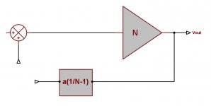
What I did was transform the initial circuit into one with a single feedback loop for analysis. That circuit is in the attachment. It is the same as I have described to Edmond above.
I then get:
FB loop gain (going around the loop): a(1-N)
FB factor (fraction of Vo returned to Vi): a((1/N)-1)
Edit: Corrected polarity of fb in attachment
Jan Didden
Attachments
janneman said:OK, we'll use 'feedback factor', defined as the fraction of Vout that is returned to Vin.
I wouldn't define it that way. I would define it as the fraction of Vout that is sensed by the feedback network. Otherwise the definition may be too architecture-specific.
I believe your transformation is in error. Would you explain your working?Also, I get the same expression for Vo/Vi for Hec as you.
But for the others I get a different one.
What I did was transform the initial circuit into one with a single feedback loop for analysis. That circuit is in the attachment. It is the same as I have described to Edmond above.
I then get:
FB loop gain (going around the loop): a(1-N)
FB factor (fraction of Vo returned to Vi): a((1/N)-1)
Edit: Corrected polarity of fb in attachment
Jan Didden
traderbam said:[snip]I believe your transformation is in error. Would you explain your working?
Ohh it's on of those standard transformations you always read about in text books. In this case, move the pos fb pick-up point from the input of N to it's output and divide by N.
But we can leave that aside if you're not comfortable with it. There's a much easier way to confirm my results. As you know, the general formula for the cl gain for a feedback amp is Gcl=N/1-N.F, where N is the forward gain as we used, and F is what is sometimes called loop transmission, or loop gain or, as you prefer, FB loop gain.
We found earlier that the cl gain for Hec is Gcl=N/(1-a+aN), so the loop transmission or FB loop gain F of course is the exact same value of a(1-N) I gave in my earlier post.
Jan Didden
- Home
- Amplifiers
- Solid State
- Bob Cordell Interview: Error Correction