Hello! Are you guys still there??
I'm all excited about getting an HP3577 10Hz-200MHz network analyzer! They're currently testing it out and getting it all shiny and stuff, I expect to get it next week.
The first task I'll use it for is to do loop gain measurements on my error correction amplifier.
As you all know, it's important to select the right point to cut the loop, so that the measurement doesn't disturb the normal operation of the circuit.
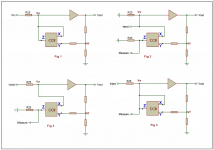
Please take a look at the attached pdf. Fig 1 is the conceptual diagram of my ec amp. The CCII sets up a current into Y which is the error, this current is conveyed to R25 so a correction voltage is added to Vin. I won't go into details, more on my website.
For doing LG measurements I would cut the loop as in Fig 2, inject the stimulus and measure the response as shown. Is this a correct way to do it?
If so, then I could just use the regular input for the stimulus as in Fig 3, of course. Then I would go to Fig 4, and when doing the measurement would just subtract the stimulus from the raw measurement to get the LG measurement. In other words, I wouldn't have to break the loop at all.
Does that make sense?
Jan Didden
I'm all excited about getting an HP3577 10Hz-200MHz network analyzer! They're currently testing it out and getting it all shiny and stuff, I expect to get it next week.
The first task I'll use it for is to do loop gain measurements on my error correction amplifier.
As you all know, it's important to select the right point to cut the loop, so that the measurement doesn't disturb the normal operation of the circuit.
Please take a look at the attached pdf. Fig 1 is the conceptual diagram of my ec amp. The CCII sets up a current into Y which is the error, this current is conveyed to R25 so a correction voltage is added to Vin. I won't go into details, more on my website.
For doing LG measurements I would cut the loop as in Fig 2, inject the stimulus and measure the response as shown. Is this a correct way to do it?
If so, then I could just use the regular input for the stimulus as in Fig 3, of course. Then I would go to Fig 4, and when doing the measurement would just subtract the stimulus from the raw measurement to get the LG measurement. In other words, I wouldn't have to break the loop at all.
Does that make sense?
Jan Didden
Attachments
janneman said:Hello! Are you guys still there??
I'm all excited about getting an HP3577 10Hz-200MHz network analyzer! They're currently testing it out and getting it all shiny and stuff, I expect to get it next week.
The first task I'll use it for is to do loop gain measurements on my error correction amplifier.
As you all know, it's important to select the right point to cut the loop, so that the measurement doesn't disturb the normal operation of the circuit.
Please take a look at the attached pdf. Fig 1 is the conceptual diagram of my ec amp. The CCII sets up a current into Y which is the error, this current is conveyed to R25 so a correction voltage is added to Vin. I won't go into details, more on my website.
For doing LG measurements I would cut the loop as in Fig 2, inject the stimulus and measure the response as shown. Is this a correct way to do it?
If so, then I could just use the regular input for the stimulus as in Fig 3, of course. Then I would go to Fig 4, and when doing the measurement would just subtract the stimulus from the raw measurement to get the LG measurement. In other words, I wouldn't have to break the loop at all.
Does that make sense?
Jan Didden
... anybody...??
janneman said:Hello! Are you guys still there??
I'm all excited about getting an HP3577 10Hz-200MHz network analyzer! They're currently testing it out and getting it all shiny and stuff, I expect to get it next week.
The first task I'll use it for is to do loop gain measurements on my error correction amplifier.
As you all know, it's important to select the right point to cut the loop, so that the measurement doesn't disturb the normal operation of the circuit.
Please take a look at the attached pdf. Fig 1 is the conceptual diagram of my ec amp. The CCII sets up a current into Y which is the error, this current is conveyed to R25 so a correction voltage is added to Vin. I won't go into details, more on my website.
For doing LG measurements I would cut the loop as in Fig 2, inject the stimulus and measure the response as shown. Is this a correct way to do it?
If so, then I could just use the regular input for the stimulus as in Fig 3, of course. Then I would go to Fig 4, and when doing the measurement would just subtract the stimulus from the raw measurement to get the LG measurement. In other words, I wouldn't have to break the loop at all.
Does that make sense?
Jan Didden
Hi Jan,
Sounds exciting!
I'm actually out West on vacation for the next week and a half, with limited connectivity.
Cheers,
Bob
janneman said:... anybody...??
Hi Jan,
You may have already seen this one, but just in case you haven't, here is a link to Middlebrook's 1975 paper where he has some discussion of this.
I'm jealous of your new acquisition 🙂. Does it have an S-parameter test set too?
Hi Andy,
Yes thanks, I do have the Middlebrook paper and did study it. In the ec setup, the positive and negative feedback loops are closely intertwined, and the combination has to be broken to measure the loop gain of course. An advantage of my particular setup is that there's very low forward gain so DC offset due to a broken loop isn't of concern - less than 50mV at the output.
There's a simple HP app note for this also. Note the 'reverse' use of a current probe to couple the test signal into the circuit.
I hope to be able to pick up the 3577 next Saturday. I didn't take the S-parameter test set. He had a 35677 but that was another 1000 euro's and had a freq range that started at 100kHz IIRC. So I let that be. For now...
Jan Didden
janneman said:Hi Andy,
Yes thanks, I do have the Middlebrook paper and did study it. In the ec setup, the positive and negative feedback loops are closely intertwined, and the combination has to be broken to measure the loop gain of course. An advantage of my particular setup is that there's very low forward gain so DC offset due to a broken loop isn't of concern - less than 50mV at the output.
There's a simple HP app note for this also. Note the 'reverse' use of a current probe to couple the test signal into the circuit.
I hope to be able to pick up the 3577 next Saturday. I didn't take the S-parameter test set. He had a 35677 but that was another 1000 euro's and had a freq range that started at 100kHz IIRC. So I let that be. For now...
Jan Didden
I have a lot of experience using 3577s. They are quite useful.
I'm wondering how you have been measuring the loop gain in simulations up to now?
janneman said:There's a simple HP app note for this also. Note the 'reverse' use of a current probe to couple the test signal into the circuit.
Ahh, thanks - looks like a good one!
Originally posted by janneman
Hello! Are you guys still there??
The first task I'll use it for is to do loop gain measurements on my error correction amplifier.
As you all know, it's important to select the right point to cut the loop, so that the measurement doesn't disturb the normal operation of the circuit.
Please take a look at the attached image.
Fig 1 is the conceptual diagram of my ec amp. The CCII sets up a current into Y which is the error, this current is conveyed to R25 so a correction voltage is added to Vin. I won't go into details, more on my website.
For doing LG measurements I would cut the loop as in Fig 2, inject the stimulus and measure the response as shown. Is this a correct way to do it?
If so, then I could just use the regular input for the stimulus as in Fig 3, of course. Then I would go to Fig 4, and when doing the measurement would just subtract the stimulus from the raw measurement to get the LG measurement. In other words, I wouldn't have to break the loop at all.
Does that make sense?
Jan Didden
Jan, it does not make much sense to me, Lineup.
I am not into such things & is not motivated to get into this.
But Mr Cordell may do this, I think, if he has got some spare time.
I attach your idea in one image.
People like them images better than PDF = more easy views
Regards, Lineup
Attachments
OK thanks. I haven't got my 3577 yet, hopefully this saturday. Ans of course my fig 4 is non-sense 😉
Jan Didden
Jan Didden
Finally got my 3577 set-up. In the process of learning it's tricks.
I think there is a problem with the intrument save/recall. If I do a save/recall, it comes back with the full freq range of 10Hz - 200MHz, rather than the range I had set when I did the save. Shouldn't that also be saved? Can't find it in the manual.
Anyway. I still would appreciate an input as to my method to measure loop gain, see attached. I think it is in line with what I read elsewere and in Middlebrook's paper. The voltage injection point has a load Z (the amp input Z) that is much higher than the source Z (the measurement signal generator).
By terminating the error current generator at node Z in an impedance equal to the impedance it sees when the loop is closed (R25), that part is also being taken care of.
So, my loop gain is the measured response (fig 3) at node Z (measure) / input signal (inject). Any comments?
Jan Didden
Attachments
janneman said:Finally got my 3577 set-up. In the process of learning it's tricks.
I think there is a problem with the intrument save/recall. If I do a save/recall, it comes back with the full freq range of 10Hz - 200MHz, rather than the range I had set when I did the save. Shouldn't that also be saved? Can't find it in the manual.
Anyway. I still would appreciate an input as to my method to measure loop gain, see attached. I think it is in line with what I read elsewere and in Middlebrook's paper. The voltage injection point has a load Z (the amp input Z) that is much higher than the source Z (the measurement signal generator).
By terminating the error current generator at node Z in an impedance equal to the impedance it sees when the loop is closed (R25), that part is also being taken care of.
So, my loop gain is the measured response (fig 3) at node Z (measure) / input signal (inject). Any comments?
Jan Didden
... nobody? Don't tell me this is over your collective heads

Jan Didden
janneman said:
... nobody? Don't tell me this is over your collective heads
Jan Didden
Hi Jan, I should use Fig. 2, but with a series impedance in the injection port as close al possible to the CCII output impedance across the measurement range, just for completness.
In Fig. 3 you do not have the CCII output impedance shunting node Ve, so measured transfer could in principle be affected, depending on whether R25 is comparable or not.
Rodolfo
ingrast said:
Hi Jan, I should use Fig. 2, but with a series impedance in the injection port as close al possible to the CCII output impedance across the measurement range, just for completness.
In Fig. 3 you do not have the CCII output impedance shunting node Ve, so measured transfer could in principle be affected, depending on whether R25 is comparable or not.
Rodolfo
Rodolfo,
Thanks for your input. Indeed I should include that. In the audio band, R25 is several orders of magnitude smaller than the CCII Zout, but at higher frequencies that may not be the case.
OTOH, the CCII Zout is in parallel with the R25 that is on the measurement node, so at that point it IS included. Maybe that is adequate.
Jan Didden
Jan,
Why don't you post the simulated loop gain as a guide to what the actual loop gain should look like?
Brian
Why don't you post the simulated loop gain as a guide to what the actual loop gain should look like?
Brian
Where is this thread? I does appear on Search but not in the Solid State front page? Others are missing as well.
syn08 said:Where is this thread? I does appear on Search but not in the Solid State front page? Others are missing as well.
It's back after posting!
syn08 said:
It's back after posting!
Hi Syn08,
I think several of the permanent threads were changed to be ordinary threads.
Cheers,
Bob
Hello Bob,
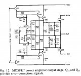
I've been playing with an ec ops similar to your fig 12 (attached), and I have a query.
The way I see it is that the ec mechanism reduces the distortion from the junction of R34 and B-Q24 to the output. This it does by varying the current drawn from that R34/Q24 node. However, the result of that is that the signal at R34/Q24 is no longer a faithfull copy of the Vas Vout: iow, the input signal to the ec loop is distorted by that loop itself.
Am I reasoning correctly here?
Jan Didden
Attachments
Hi Edmond,
What a pleasant surprise! A new post in this thread since many days and bang! you're there. As if you were lurking for it (which you weren't of course, you were putting up wallpaper, right 😉 ).
Yes I *think* I know what you mean, I probably know Hawksfords paper by heart. But it keeps coming back at me all the time.
As you probably remember I used his concept in my paX amplifier, so I am familiar with it somewhat.
What I keep marvelling at is this. The signal at that R34/Q24 node is distorted by the EC. Still, the final result (in the ideal case) is that Vout is identical to Vin. Since the EC 'input' is connected to it's 'control' node, it can't really null out the distortion between it's input and the output. So what apparently happens is that it 'pre-distorts' the R34/Q24 node just enough so that, in combination with the intrinsic distortion of the ops, the result is perfect linearity (in the ideal case).
And it does that 'perfect pre-distortion' without having access to the Vin in the first place. Isn't that marvellous?
I was hoping Bob would have a view that was new to me to help me assimilate it better. I just hope you didn't scare him off. Then again, I find that Bob isn't a man who scares easily...
Jan Didden
- Home
- Amplifiers
- Solid State
- Bob Cordell Interview: Error Correction