O.T.
Hi Klaus,
/OT on
Wow, that's really big.
BTW, did you see the 'can crusher' as well?
http://tesladownunder.com/CanCrushing.htm#Can crusher 3
Funny, isn't it?
/OT off
Cheers.
Hi Klaus,
/OT on
Wow, that's really big.
BTW, did you see the 'can crusher' as well?
http://tesladownunder.com/CanCrushing.htm#Can crusher 3
Funny, isn't it?
/OT off
Cheers.
Edmond Stuart said:
Hi Glen,
I know about that speaker (only the bass unit had NFB by means of a piezo accelero transducer), but it wasn't me who designed it.
Cheers,
Edmond.
That's the one. It's an interesting design. If I can find the magazine this weekend (It's in a pile of 100's) I'll post up the schematic.
Cheers,
Glen
real global NFB
Hi Glen,
If you can find it, please, post it.
BTW, the piezo element, together with a FET (common source, common drain?) was mounted in the center of the cone. The latter provided a signal for negative feedback. Now this is what I would call global NFB. 😀
Cheers,
Edmond.
PS: A new girlfriend? Was Rachel getting too old?
G.Kleinschmidt said:That's the one. It's an interesting design. If I can find the magazine this weekend (It's in a pile of 100's) I'll post up the schematic.
Cheers,
Glen
Hi Glen,
If you can find it, please, post it.
BTW, the piezo element, together with a FET (common source, common drain?) was mounted in the center of the cone. The latter provided a signal for negative feedback. Now this is what I would call global NFB. 😀
Cheers,
Edmond.
PS: A new girlfriend? Was Rachel getting too old?
Re: real global NFB
Ménage à trois!
😀
Edmond Stuart said:PS: A new girlfriend? Was Rachel getting too old?
Ménage à trois!
😀
Re: WEC
as in the 797.
no.Edmond Stuart said:WEC? Do you mean EC by means of an AFA (Active Feedback Amplifier)?
Cheers,
Edmond.
as in the 797.
Re: Re: Re: real global NFB
That's only a problem for old fogies like you!
😀
Edmond Stuart said:
Mind your heart 😉
That's only a problem for old fogies like you!
😀
Re: Re: patent 4785257
Hi Bob,
As I told you already, this doesn't work and, of course, it has nothing to with my concern of loading of the VAS output with the Miller capacitor. The reason why it doesn't work is quite simple: the signal at the pre-driver emitter is a bit distorted. Feeding this signal (via a Miller cap) back to the VAS input, thereby bypassing the EC circuit, will ruin the error correction.
To make it easier for you to verify my assertion, I did the same with your EC amp. Tying C4 (20pF) to the emitter of Q24/Q25 increases the THD20 from 6 to 94ppm and, not surprisingly, I got the same increase by simply disabling the EC stage.
Cheers,
Edmond.
Bob Cordell said:Hi Edmond,
These are good points, but I think that the concern about loading the VAS with a Miller compensation capacitor would be eliminated if the capacitor was tapped off from the pre-driver emitter follower that comes after the VAS.
...................................................
Next post:
Then I guess your concern about loading of the VAS with the Miller capacitor was unfounded and not the source of distortion.
Cheers,
Bob
Hi Bob,
As I told you already, this doesn't work and, of course, it has nothing to with my concern of loading of the VAS output with the Miller capacitor. The reason why it doesn't work is quite simple: the signal at the pre-driver emitter is a bit distorted. Feeding this signal (via a Miller cap) back to the VAS input, thereby bypassing the EC circuit, will ruin the error correction.
To make it easier for you to verify my assertion, I did the same with your EC amp. Tying C4 (20pF) to the emitter of Q24/Q25 increases the THD20 from 6 to 94ppm and, not surprisingly, I got the same increase by simply disabling the EC stage.
Cheers,
Edmond.
Re: Re: Re: patent 4785257
Hi Edmond,
Insofar as my EC amplifier goes, you have missed the boat completely. How could you miss this?? Of COURSE you don't take the Miller compensation off of the emitters of Q24/25!!! You take it off of Q20/21! C'mon, Edmond, isn't that obvious?
You seem to have been confused by the semantics of "pre-driver". You should pay closer attention to how things are supposed to work before you make your criticisms.
Cheers,
Bob
Edmond Stuart said:
Hi Bob,
As I told you already, this doesn't work and, of course, it has nothing to with my concern of loading of the VAS output with the Miller capacitor. The reason why it doesn't work is quite simple: the signal at the pre-driver emitter is a bit distorted. Feeding this signal (via a Miller cap) back to the VAS input, thereby bypassing the EC circuit, will ruin the error correction.
To make it easier for you to verify my assertion, I did the same with your EC amp. Tying C4 (20pF) to the emitter of Q24/Q25 increases the THD20 from 6 to 94ppm and, not surprisingly, I got the same increase by simply disabling the EC stage.
Cheers,
Edmond.
Hi Edmond,
Insofar as my EC amplifier goes, you have missed the boat completely. How could you miss this?? Of COURSE you don't take the Miller compensation off of the emitters of Q24/25!!! You take it off of Q20/21! C'mon, Edmond, isn't that obvious?
You seem to have been confused by the semantics of "pre-driver". You should pay closer attention to how things are supposed to work before you make your criticisms.
Cheers,
Bob
Re: Re: Re: Re: patent 4785257
Hi Bob,
I'm glad we agree on one thing at least: using Q20/21 instead of Q24/25 and for me, that's obvious right from the beginning. But apparently not for you, otherwise you hadn't post #3425.
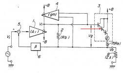
And I'm certainly not confused by the semantics of "pre-driver". If you read the patent (apparently, you still haven't done that), you will see that there is only one pre-driver (see figure, red arrow), so no confusion at all. Tying the Miller cap to this pre-driver spoils the whole thing in exactly the same way as tying the cap to Q24/25 in your amp. Happily you see why this is totally wrong. I also hope that you will understand why I had tied the cap to Q24/25, just as an example of bad practice.
Now that I have made that clear, you will certainly understand why your suggestion in post #3425 doesn't work either. That's the only thing I'm trying and willing to point out.
Cheers,
Edmond.
I almost forgot: You should pay closer attention to how things are supposed to work (and read that f*cking patent) before you make your criticisms.
Bob Cordell said:Hi Edmond,
Insofar as my EC amplifier goes, you have missed the boat completely. How could you miss this?? Of COURSE you don't take the Miller compensation off of the emitters of Q24/25!!! You take it off of Q20/21! C'mon, Edmond, isn't that obvious?
You seem to have been confused by the semantics of "pre-driver". You should pay closer attention to how things are supposed to work before you make your criticisms.
Cheers,
Bob
Hi Bob,
I'm glad we agree on one thing at least: using Q20/21 instead of Q24/25 and for me, that's obvious right from the beginning. But apparently not for you, otherwise you hadn't post #3425.
And I'm certainly not confused by the semantics of "pre-driver". If you read the patent (apparently, you still haven't done that), you will see that there is only one pre-driver (see figure, red arrow), so no confusion at all. Tying the Miller cap to this pre-driver spoils the whole thing in exactly the same way as tying the cap to Q24/25 in your amp. Happily you see why this is totally wrong. I also hope that you will understand why I had tied the cap to Q24/25, just as an example of bad practice.
Now that I have made that clear, you will certainly understand why your suggestion in post #3425 doesn't work either. That's the only thing I'm trying and willing to point out.
Cheers,
Edmond.
I almost forgot: You should pay closer attention to how things are supposed to work (and read that f*cking patent) before you make your criticisms.
Attachments
Edmond,
Hawksford EC relies on balance of R34, R35, R40-45, once you are moving Miller cap output impedances of Q20, Q21 (base impedance divide by beta) ruin balance equation.
Hawksford EC relies on balance of R34, R35, R40-45, once you are moving Miller cap output impedances of Q20, Q21 (base impedance divide by beta) ruin balance equation.
Re: Re: Re: Re: patent 4785257
Nice try Bob, but I'm afraid its useless. The topic contains at least two keywords (EC and Hawksword) that are known to trigger impulses to burn, nuke, annihilate, etc... the playground by any means and at any cost.
Bob Cordell said:
Hi Edmond,
Insofar as my EC amplifier goes, you have missed the boat completely. How could you miss this?? Of COURSE you don't take the Miller compensation off of the emitters of Q24/25!!! You take it off of Q20/21! C'mon, Edmond, isn't that obvious?
You seem to have been confused by the semantics of "pre-driver". You should pay closer attention to how things are supposed to work before you make your criticisms.
Cheers,
Bob
Nice try Bob, but I'm afraid its useless. The topic contains at least two keywords (EC and Hawksword) that are known to trigger impulses to burn, nuke, annihilate, etc... the playground by any means and at any cost.
dimitri said:Edmond,
Hawksford EC relies on balance of R34, R35, R40-45, once you are moving Miller cap output impedances of Q20, Q21 (base impedance divide by beta) ruin balance equation.
Hi Dimitri,
Connecting Miller caps to the emitters of Q20/21 has some effect on the balance, but, since the impedance at these nodes is already very low, the effect is not that much, only a few Ohms. So it will not 'ruin' the balance equation.
BTW, why are you telling this to me? It was Bob's idea, not mine.
Cheers,
Edmond.
please explain whysince the impedance at these nodes is already very low
misreading, it was my impression that you advocated itwhy are you telling this to me? It was Bob's idea, not mine
Hi Dimitri,
Low, because the output impedance of the VAS (let's call it Zo) is also rather low, particular at higher frequencies as result of the NFB action of the Miller cap. I don't know precise numbers at the moment, but I guess Zo = 50...200 Ohm @ 20kHz. Looking at the emitter of Q20/21, you may divide Zo by beta, and you will get a few Ohms.
Moving the Miller cap to Q20/21 (i.e. two caps of 10pF, one for each emitter) has roughly the same impedance lowering effect at these nodes. That's all, nothing special.
Cheers,
Edmond.
PS: Of course I've verified by means of a sim that the EC balance was hardly disturbed.
- Home
- Amplifiers
- Solid State
- Bob Cordell Interview: Error Correction