CFP vs HEC
Hi Hugh,
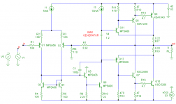
To avoid any confusion, have a look at the picture below. Is this what you mean? If so, I don't feel qualified enough to pass a definitive judgment, as I don't have any experience with this kind of output stages.
Nevertheless I did a quick simulation of this circuit, and indeed, it's more prone to instability. The unity gain frequency of the local feedback loop around the OPS is quite high and the phase margin rather low (sorry, I don't give you the exact numbers as I don't know how reliable they are).
Anyhow, to get this amp stable one should keep the lead inductances of the output devices as low as possible and take care of sufficient HF decoupling of the supply rails.
BTW, I don't think you can avoid these problems by adjusting the lag compensation to the VAS, as it's a local problem around the OPS and the Ft of this local loop is much higher than the Ft of the global NFB loop.
Regarding the distortion, I have made a remarkable observation: The THD20 is below 10ppm in class-A or B, but in class-AB 10 to 30 times higher (depending on the quiescent current).
Apart from stability issues, this topology doesn't excel in turn off switching of the output devices, resulting in cross conduction at steep transients.
All in all, it is not my favorite OPS, despite the fact that in terms of THD it comes close to HEC.
I hope that somebody else will jump in and share his real life experience with you.
Cheers, Edmond.
AKSA said:Edmond,
Thank you for your answer, and your attempts to explain to me the worthiness of EC, much appreciated.
This conflict with Robert is absurd. You are both very decent technocrats. Please, put it behind you and move on!
May I ask another question? Ordinarily the Vbe distortion of the double EF output stage is largely produced by the output device itself, whose Vbe runs from 600mV at no signal to around 1.8V at 5A. These voltages are easy to divine from the device curves, of course. But there is also a contribution from the drivers, which might run to 400mA collector current with a four pair output stage. This might only be from 600mV to 800mV, but it does contribute to Vbe compression nonetheless.
What about using a CFP driver stage, wherein the pre-driver controls the Vbe which stays essentially unchanged due to the very small current changes in this first device? (Some attempt should be made to keep this CFP stage on at all times.) This would reduce driver stage distortion to virtually zero...... and might deliver very high, EC style input impedance to the stage as a whole.
My concern is the stability of EC. It appears to me that it usually requires revision of the lag comp to the VAS, and this is a PITA.
Cheers,
Hugh
Hi Hugh,
To avoid any confusion, have a look at the picture below. Is this what you mean? If so, I don't feel qualified enough to pass a definitive judgment, as I don't have any experience with this kind of output stages.
Nevertheless I did a quick simulation of this circuit, and indeed, it's more prone to instability. The unity gain frequency of the local feedback loop around the OPS is quite high and the phase margin rather low (sorry, I don't give you the exact numbers as I don't know how reliable they are).
Anyhow, to get this amp stable one should keep the lead inductances of the output devices as low as possible and take care of sufficient HF decoupling of the supply rails.
BTW, I don't think you can avoid these problems by adjusting the lag compensation to the VAS, as it's a local problem around the OPS and the Ft of this local loop is much higher than the Ft of the global NFB loop.
Regarding the distortion, I have made a remarkable observation: The THD20 is below 10ppm in class-A or B, but in class-AB 10 to 30 times higher (depending on the quiescent current).
Apart from stability issues, this topology doesn't excel in turn off switching of the output devices, resulting in cross conduction at steep transients.
All in all, it is not my favorite OPS, despite the fact that in terms of THD it comes close to HEC.
I hope that somebody else will jump in and share his real life experience with you.
Cheers, Edmond.
Attachments
Edmond,
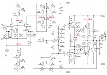
Regarding CFP driver instead of an classic T output stage, please read this thread. It is my latest amplifier and it sound very very good.
It is also rock solid from stability POV.
http://www.diyaudio.com/forums/showthread.php?s=&threadid=111756
Mihai
Regarding CFP driver instead of an classic T output stage, please read this thread. It is my latest amplifier and it sound very very good.
It is also rock solid from stability POV.
http://www.diyaudio.com/forums/showthread.php?s=&threadid=111756
Mihai
Attachments
Re: Re: soap
Hi Terry,
I don't think there is any disagreement between us, as it rather obvious that the heavier the load the more an amp benefits from a VAS buffer.
Now, that being the case, what's your answer to the original question of Hugh (see post 3058) if extreme loads come into play?
Cheers, Edmond.
Terry Demol said:WRT buffered VAS, I have been looking into this a little further.
I did say I agreed "to a point" and it appears, as always there are
exceptions.
[snip]
cheers
Terry
Hi Terry,
I don't think there is any disagreement between us, as it rather obvious that the heavier the load the more an amp benefits from a VAS buffer.
Now, that being the case, what's your answer to the original question of Hugh (see post 3058) if extreme loads come into play?
Cheers, Edmond.
It is my latest amplifier and it sound very very good.
Glad to hear that this one sounds good, but you are 30 years late, Mihai
4,176,323
Attachments

Dimitri,
My amp is folded cascode and I do not make money from this .😉
I don't care about reinventing the wheel as long as it deliver big $ sound at a modest price.
Mihai
sorry for offtopic
My amp is folded cascode and I do not make money from this .😉
I don't care about reinventing the wheel as long as it deliver big $ sound at a modest price.
Mihai
sorry for offtopic
VAS buffer
Hi Dimtri,
I'm afraid that Douglas Self will disagree with your figures.
His 'load invariant' amp for example (EW, Jan.1997, pp. 16-24) distorts only -100dB. Above 2kHz it rises steadily to -88dB at 20kHz.
I guess that your figures are based on a rather lame VAS, ie comprising only one tranny. In that case the output impedance of the VAS is much higher and of course, a buffer will have a greater impact.
There are lots of different VASses around here, with OP impedances varying from 25 Ohm to several KOhms at 20kHz. It is this impedance that greatly determines how far a VAS buffer is beneficial. Obviously, with zero impedance, a buffer does nothing.
Therefore, this whole discussion on the blessings of a VAS buffer is pointless without an accurate description of the VAS or at least a mention of its output impedance.
Cheers, Edmond.
dimitri said:That is absolutely correct, with dual EF distortion is above -70…80 dB with conventional direct path. With triple EF it would be on -100dB level. I’m talking about OFB design.
Hi Dimtri,
I'm afraid that Douglas Self will disagree with your figures.
His 'load invariant' amp for example (EW, Jan.1997, pp. 16-24) distorts only -100dB. Above 2kHz it rises steadily to -88dB at 20kHz.
I guess that your figures are based on a rather lame VAS, ie comprising only one tranny. In that case the output impedance of the VAS is much higher and of course, a buffer will have a greater impact.
There are lots of different VASses around here, with OP impedances varying from 25 Ohm to several KOhms at 20kHz. It is this impedance that greatly determines how far a VAS buffer is beneficial. Obviously, with zero impedance, a buffer does nothing.
Therefore, this whole discussion on the blessings of a VAS buffer is pointless without an accurate description of the VAS or at least a mention of its output impedance.
Cheers, Edmond.
roender said:Edmond,
Regarding CFP driver instead of an classic T output stage, please read this thread. It is my latest amplifier and it sound very very good.
It is also rock solid from stability POV.
http://www.diyaudio.com/forums/showthread.php?s=&threadid=111756
Mihai
Hi Mihai,
It looks great, and no doubt it sounds good and is rock solid.
But the OPS is different from the one I've posted and is probably more stable.
Cheers, Edmond.
Edmond,
My amplifier has the CFP driver in output stage as the one mentioned by Hugh. Also, the driver bias current is very high.
http://www.diyaudio.com/forums/showthread.php?postid=1407000#post1407000
My amplifier has the CFP driver in output stage as the one mentioned by Hugh. Also, the driver bias current is very high.
http://www.diyaudio.com/forums/showthread.php?postid=1407000#post1407000
roender said:Edmond,
My amplifier has the CFP driver in output stage as the one mentioned by Hugh. Also, the driver bias current is very high.
http://www.diyaudio.com/forums/showthread.php?postid=1407000#post1407000
Hi Mihai,
Perhaps I've misunderstood Hugh. That's why I dropped a schematic for conformation. Let's wait for his reply.
If I'm wrong you are the man to answer all his questions
Cheers, Edmond.
I guess that your figures are based on a rather lame VAS, ie comprising only one tranny. In that case the output impedance of the VAS is much higher and of course, a buffer will have a greater impact.
There are lots of different VASses around here, with OP impedances varying from 25 Ohm to several KOhms at 20kHz. It is this impedance that greatly determines how far a VAS buffer is beneficial. Obviously, with zero impedance, a buffer does nothing.
Assuming VAS is CE stage, the OP impedance can be lowered by shunt FB (Miller, resisitor, 2poles + 1zero). What is the healthy VAS?
VAS
Hi Dimitri,
Indeed, the OP impedance can be considerably lowered by the Miller cap, provided that there is sufficient gain inside the VAS. Therefore I prefer an additional "beta enhancement tranny" (not to be confused with a Darlington), which also has a positive effect on the amount of "pole splitting".
What is a healthy VAS? If it is a Voltage Amplifying Stage. 🙂 More precisely, if the output behaves as a voltage source and not as a current source (not counting exceptions). At least, this is my opinion.
Cheers, Edmond.
dimitri said:Assuming VAS is CE stage, the OP impedance can be lowered by shunt FB (Miller, resisitor, 2poles + 1zero). What is the healthy VAS?
Hi Dimitri,
Indeed, the OP impedance can be considerably lowered by the Miller cap, provided that there is sufficient gain inside the VAS. Therefore I prefer an additional "beta enhancement tranny" (not to be confused with a Darlington), which also has a positive effect on the amount of "pole splitting".
What is a healthy VAS? If it is a Voltage Amplifying Stage. 🙂 More precisely, if the output behaves as a voltage source and not as a current source (not counting exceptions). At least, this is my opinion.
Cheers, Edmond.
Thanks, Edmond
Can this "beta enhancement tranny" be found in your non-HEC-amp? What it is - new name for Sziklai pair? Why do you need high beta for low output VAS impedance?
Can this "beta enhancement tranny" be found in your non-HEC-amp? What it is - new name for Sziklai pair? Why do you need high beta for low output VAS impedance?
dimitri said:Thanks, Edmond
Can this "beta enhancement tranny" be found in your non-HEC-amp? What it is - new name for Sziklai pair? Why do you need high beta for low output VAS impedance?
Hi Dimitri,
D. Self has invented this terminology.
in your non-HEC-amp? Yes, but that schematic might be confusing, as these trannies are also part of the common mode control loop.
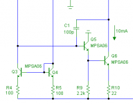
You better have a look at fig. 4-C, first tranny in
http://www.automotivedesignline.com...ionid=EPDM5XFSMAA3YQSNDLRSKH0CJUNN2JVN?pgno=1
(the other pages are also worth reading)
It is not a Sziklai pair, rather a Darlington with the collectors NOT tied together.
Why do you need high beta? For more Miller loop gain, resulting in lower OP impedance, about ten times.
Cheers, Edmond.
I need to double check with Solomon, J.: "The Monolithic Op Amp: A Tutorial Study", IEEE Journal of Solid. State Circuits, December 1974, pp. 314-332 but my understanding is that the VAS OP impedance will be lower with higher Gm, not current gain.
Darlington with the collectors NOT tied together was used in uA741 e.g. see here (and some relevant analysis):
http://web.mit.edu/klund/www/papers/ACC04_opcomp.pdf
Darlington with the collectors NOT tied together was used in uA741 e.g. see here (and some relevant analysis):
http://web.mit.edu/klund/www/papers/ACC04_opcomp.pdf
VAS
Hi Dimitri,
I've checked and double checked the OP impedances again:
Here are the results:
At 1kHz 1 tranny: 4.2kOhm
At 1kHz 2 trannies: 296 Ohm
At 20kHz 1 tranny: 221 Ohm
At 20kHz 2 trannies: 42.5 Ohm
I guess that more factors are involved, than only current gain. Besides, if it had no effect, why should D. Self highly recommend this "beta enhancement" thingy?
Cheers, Edmond.
dimitri said:I need to double check with Solomon, J.: "The Monolithic Op Amp: A Tutorial Study", IEEE Journal of Solid. State Circuits, December 1974, pp. 314-332 but my understanding is that the VAS OP impedance will be lower with higher Gm, not current gain.
Darlington with the collectors NOT tied together was used in uA741 e.g. see here (and some relevant analysis):
http://web.mit.edu/klund/www/papers/ACC04_opcomp.pdf
Hi Dimitri,
I've checked and double checked the OP impedances again:
Here are the results:
At 1kHz 1 tranny: 4.2kOhm
At 1kHz 2 trannies: 296 Ohm
At 20kHz 1 tranny: 221 Ohm
At 20kHz 2 trannies: 42.5 Ohm
I guess that more factors are involved, than only current gain. Besides, if it had no effect, why should D. Self highly recommend this "beta enhancement" thingy?
Cheers, Edmond.
Attachments
I guess that more factors are involved, than only current gain.
In this particular embodiment the feedback ratio will be (h21(Q5)*h21(Q10)*R10||ZcQ3)/(h21(Q5)*h21(Q10)*R10||ZcQ3+ZC1)
So the explanation is that the higher current gain allows higher input resistance of the VAS thus higher local loop gain around VAS and lower OP impedance. Good.
Thank you, Edmond
dimitri said:In this particular embodiment the feedback ratio will be (h21(Q5)*h21(Q10)*R10||ZcQ3)/(h21(Q5)*h21(Q10)*R10||ZcQ3+ZC1)
So the explanation is that the higher current gain allows higher input resistance of the VAS thus higher local loop gain around VAS and lower OP impedance. Good.
Thank you, Edmond
Thank you too, Dimitri.
Re: VAS
Hi Edmond,
I know that, through laziness, I often refer to an emitter follower preceding the VAS transistor as a Darlinton; it is not, as a true Darlington would have its collector connected to the collector of the VAS, rather than supply.
Are you referring to the "beta enhancement" transistor as an EF driving the VAS transistor?
BTW, my favorite VAS standing current is about 10 mA, with the VAS CE transistor degenerated with about 22 ohms. Thus, I don't dissipate too much power in the VAS. This kind of arrangement likes to see a Triple in the output stage.
Cheers,
Bob
Edmond Stuart said:
Hi Dimitri,
Indeed, the OP impedance can be considerably lowered by the Miller cap, provided that there is sufficient gain inside the VAS. Therefore I prefer an additional "beta enhancement tranny" (not to be confused with a Darlington), which also has a positive effect on the amount of "pole splitting".
What is a healthy VAS? If it is a Voltage Amplifying Stage. 🙂 More precisely, if the output behaves as a voltage source and not as a current source (not counting exceptions). At least, this is my opinion.
Cheers, Edmond.
Hi Edmond,
I know that, through laziness, I often refer to an emitter follower preceding the VAS transistor as a Darlinton; it is not, as a true Darlington would have its collector connected to the collector of the VAS, rather than supply.
Are you referring to the "beta enhancement" transistor as an EF driving the VAS transistor?
BTW, my favorite VAS standing current is about 10 mA, with the VAS CE transistor degenerated with about 22 ohms. Thus, I don't dissipate too much power in the VAS. This kind of arrangement likes to see a Triple in the output stage.
Cheers,
Bob
Re: VAS
Its worth pointing out here that the lower output impedance of the Miller-compensated VAS happens as a result of the higher total beta AND the fact that the VAS combination is being driven by a current mirror whose output impedance is high. Input stages that are loaded by a resistor instead of a current mirror lose out in this regard, as the loop gain involving the Miller capacitor is ultimately limited by that load resistance even if the VAS net beta goes to infinity.
Cheers,
Bob
Edmond Stuart said:
Hi Dimitri,
Indeed, the OP impedance can be considerably lowered by the Miller cap, provided that there is sufficient gain inside the VAS. Therefore I prefer an additional "beta enhancement tranny" (not to be confused with a Darlington), which also has a positive effect on the amount of "pole splitting".
What is a healthy VAS? If it is a Voltage Amplifying Stage. 🙂 More precisely, if the output behaves as a voltage source and not as a current source (not counting exceptions). At least, this is my opinion.
Cheers, Edmond.
dimitri said:
In this particular embodiment the feedback ratio will be (h21(Q5)*h21(Q10)*R10||ZcQ3)/(h21(Q5)*h21(Q10)*R10||ZcQ3+ZC1)
So the explanation is that the higher current gain allows higher input resistance of the VAS thus higher local loop gain around VAS and lower OP impedance. Good.
Thank you, Edmond
Its worth pointing out here that the lower output impedance of the Miller-compensated VAS happens as a result of the higher total beta AND the fact that the VAS combination is being driven by a current mirror whose output impedance is high. Input stages that are loaded by a resistor instead of a current mirror lose out in this regard, as the loop gain involving the Miller capacitor is ultimately limited by that load resistance even if the VAS net beta goes to infinity.
Cheers,
Bob
Re: Re: VAS

And that is precisely the reason why I'm so crazy about a common mode control loop (CMCL) of a symmetrical VAS, as this one does NOT spoil the VAS input by a resistor.
Cheers, Edmond.
PS: As for your favorite VAS, see my last picture. 😀
Bob Cordell said:Its worth pointing out here that the lower output impedance of the Miller-compensated VAS happens as a result of the higher total beta AND the fact that the VAS combination is being driven by a current mirror whose output impedance is high. Input stages that are loaded by a resistor instead of a current mirror lose out in this regard, as the loop gain involving the Miller capacitor is ultimately limited by that load resistance even if the VAS net beta goes to infinity.
Cheers,
Bob
And that is precisely the reason why I'm so crazy about a common mode control loop (CMCL) of a symmetrical VAS, as this one does NOT spoil the VAS input by a resistor.
Cheers, Edmond.
PS: As for your favorite VAS, see my last picture. 😀
- Home
- Amplifiers
- Solid State
- Bob Cordell Interview: Error Correction