jcx wrote:
I agree. 🙂
I wouldn't accuse Hawksford of malfeasance, only over enthusiasm that should have been tempered by greater diligence in searching out prior works - missing the occasional obscure decades old paper is excusable, "text book" level control theory less so
I'm quite happy to have Bob's implementation of "error correction" available - I just cringe at the posts imputing magical potential to it when its equivalence to single loop error feedback lets us use Bode's negative feedback theory to find very well determined limits
I agree. 🙂
Klaus wrote:
Reminds me of servo-assisted brakes in a car. If the servo is disabled, as when the engine is not running, the brake pedal still repsonds but requires greater force.
In this sense my sketch is that of a servo-assisted output stage and if you accept that then if follows that HEC is a servo system.
Brian
Interesting observation, Klaus. I was tempted after I posted that to call it a servo but I wasn't certain of the definition of a servo. I did a web search and found a few of definitions none of which adequately distinguished a servo from any other NFB control. Your assessment rings true to me (or doesn't ring in a well adjusted circuit).WRT Brian's sketch in #2871, I see this uses same topology as a conventional DC servo. Except that the reference is not GND but the input, and the "DC" extends into the MHz. We could read "DC" as "Difference Component", though, and the integrating servo tries to null it... and to judge the stability of a DC servo I always use bode plots...
Reminds me of servo-assisted brakes in a car. If the servo is disabled, as when the engine is not running, the brake pedal still repsonds but requires greater force.
In this sense my sketch is that of a servo-assisted output stage and if you accept that then if follows that HEC is a servo system.
Brian
Re: Re: Re: Re: Re: Re: hec != hoax ?
Hi Bob,
Indeed, I took the wrong paper, but as you didn't told me which paper exactly, I hope you will forgive me my gross error.
Cheers, Edmond.
Bob Cordell said:Hi Edmond,
You asserted that Vanderkooy and Lipshitz discussed HEC before I published my paper. That was wrong. That is all.
[snip]
Cheers,
Bob
Hi Bob,
Indeed, I took the wrong paper, but as you didn't told me which paper exactly, I hope you will forgive me my gross error.
Cheers, Edmond.
scott wurcer said:FWIW, I think there's some irony to the fact that Edmond's output stage (left one) is almost device for device identical to one used in some popular line drivers for DSL (millions installed).
So some of you might have it right under your noses (so to speak). 🙂
BTW there are passive error neutralization techniques that work and can be shown to not use/be NFB and are "invisible" to the main loop frequency response.
Edit - Of course the bi-polar line drivers do not use MOSFETs, but same circuit with power NPN's and PNP's. Power in this case still smallish but the modulation of quiescent current to peak current is >200x.
Hi Scott,
Indeed, the similarity is striking. If we just add MOSFET source followers behind the output stage of the AD823, we get essentially the same circuit.
Cheers, Edmond.
KSTR said:Edmond,
Not being an expert I can't see the similarities to the AD823. There I see two buffers driving current (push-pull) into resistors and those currents are mirrored into the bases of the output trannies...
- Klaus
Hi Klaus,
I presume that Scott was only referring to the right part of the circuit, see below.
Cheers, Edmond.
Attachments
Actually not quite, but you get the idea. I found my AES preprint 1992 #3231 where I show passive (a single capacitor) neutralization of output stage dynamic Vbe error. Real scope photos on a real circuit. At the time I didn't know what a pit of vipers I was getting into. This EC stuff already had a long history and I was challenging the hegemony. I'm convinced it would work on a power amp just as well as either NFB or the HEC circuits. Someone here encouraged me and I might just build one when my plate is cleaner.
BTW, the same idea gave Walt Jung's super regulator an output impedance flat at .000001 Ohm out to 100kHz.
BTW, the same idea gave Walt Jung's super regulator an output impedance flat at .000001 Ohm out to 100kHz.
Re: Re: hec != hoax ?
Hi Bob,
I'm afraid that I have to disappoint you a little bit, as I am using TMC. Without TMC I get (of course) the same distortion as from your amp.
Are you still interested in a (basic) schematic etc.?
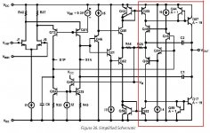
Anyhow, here are some details:
A single O/P pair biased at 150mA
100W into 8 Ohm (clipping at 120W or 44V)
Main supply voltage +/- 50V
Front-end supply voltage +/- 45V (regulated)
The front-end comprises a CFB I/P stage and a complementary VAS, biased by means of a simplified common mode control loop.
Notice that I have given the output stage a little bit of gain (1.3x) so that there is enough headroom for stabilizing the front-end supply lines and (optional) cascodes in the VAS.
Cheers, Edmond.
Bob Cordell said:Hi Edmond,
Thanks for doing this. I also had a hunch that 1 ppm could be reached by HEC + NFB alone, but I have not yet done a sim of it, just some back of the envelope of my individual results of my VAS and EC OPS.
Can you share the schematic and details with us?
I assume that you did not use TMC, is that correct?
Was the THD-20 100W into 8 ohms with a single output pair biased at 150 mA? Or was it 200W into 4 ohms with three output pairs biased at a total of 450 mA? Or something else?
Can you show us the fourier spectrum?
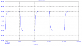
Can you show us the 100 kHz square wave response?
I assume you used the same rail voltages throughout; what were the rail voltages and at what peak voltage did the amp clip?
Thanks,
Bob
Hi Bob,
I'm afraid that I have to disappoint you a little bit, as I am using TMC. Without TMC I get (of course) the same distortion as from your amp.
Are you still interested in a (basic) schematic etc.?
Anyhow, here are some details:
A single O/P pair biased at 150mA
100W into 8 Ohm (clipping at 120W or 44V)
Main supply voltage +/- 50V
Front-end supply voltage +/- 45V (regulated)
The front-end comprises a CFB I/P stage and a complementary VAS, biased by means of a simplified common mode control loop.
Notice that I have given the output stage a little bit of gain (1.3x) so that there is enough headroom for stabilizing the front-end supply lines and (optional) cascodes in the VAS.
Cheers, Edmond.
Attachments
BTW Edmond, Bob
Both you guys (and others like andy, etc.) are doing some first rate stuff, even if it does get punctuated by some needless controversy.
Both you guys (and others like andy, etc.) are doing some first rate stuff, even if it does get punctuated by some needless controversy.
scott wurcer said:BTW Edmond, Bob
Both you guys (and others like andy, etc.) are doing some first rate stuff, even if it does get punctuated by some needless controversy.
Thanks Scott.
Re: Re: Re: hec != hoax ?
Hi Edmond,
As always, thanks for this information.
I would be interested in seeing it, if you get around to it. If possible, I'm also interested in the FFT spectrum. Some of these techniques being used may not always yield as civilized a spectrum as we would like.
Cheers,
Bob
Edmond Stuart said:
Hi Bob,
I'm afraid that I have to disappoint you a little bit, as I am using TMC. Without TMC I get (of course) the same distortion as from your amp.
Are you still interested in a (basic) schematic etc.?
Anyhow, here are some details:
A single O/P pair biased at 150mA
100W into 8 Ohm (clipping at 120W or 44V)
Main supply voltage +/- 50V
Front-end supply voltage +/- 45V (regulated)
The front-end comprises a CFB I/P stage and a complementary VAS, biased by means of a simplified common mode control loop.
Notice that I have given the output stage a little bit of gain (1.3x) so that there is enough headroom for stabilizing the front-end supply lines and (optional) cascodes in the VAS.
Cheers, Edmond.
Hi Edmond,
As always, thanks for this information.
I would be interested in seeing it, if you get around to it. If possible, I'm also interested in the FFT spectrum. Some of these techniques being used may not always yield as civilized a spectrum as we would like.
Cheers,
Bob
scott wurcer said:BTW Edmond, Bob
Both you guys (and others like andy, etc.) are doing some first rate stuff, even if it does get punctuated by some needless controversy.
Thanks very much, Scott. Although Edmond and I don't always agree, I can certainly say that he has inspired me and pushed me to think harder about a lot of things, and work harder at refining performance and understanding. I hope the reverse is true as well. Much of this would not be possible without the help of others like Andy with the models. That sort of interaction is a big part of the value of this board.
Cheers,
Bob
Re: Re: Re: Re: hec != hoax ?
Your're welcome.
Hi Bob,
Although I like to share this info with you, you still hasn't answered my question (regarding HEC): what does the other point of view reveals in terms of stability, distortion reduction etc. ?
Cheers, Edmond.
Bob Cordell said:Hi Edmond,
As always, thanks for this information.
Your're welcome.
I would be interested in seeing it, if you get around to it. If possible, I'm also interested in the FFT spectrum. Some of these techniques being used may not always yield as civilized a spectrum as we would like.
Cheers, Bob
Hi Bob,
Although I like to share this info with you, you still hasn't answered my question (regarding HEC): what does the other point of view reveals in terms of stability, distortion reduction etc. ?
Cheers, Edmond.
Re: Re: Re: Re: Re: hec != hoax ?
Hello Edmond.
I have also busted through the 1ppm THD-20 barrier (300W 4ohm) in simulation with my class A amp, which keeps evolving.
Still no EC, but now a full bridge design (now fully symmetrical along the y axis as well as the x 🙂 )
Basically the circuit I presented in the PGP thread, but everything on the right hand side of the JFET/CFP input buffer pair duplicated/mirrored on the left hand side. A CMV servo biases the thing by steering the currents which establish the VAS biasing voltages across the 3k LTP load resistors. There is also a little DC NFB around each VAS stage to make sure that the LF gains of each bridge half track well.
Cheers,
Glen
Edmond Stuart said:
Your're welcome.
Hi Bob,
Although I like to share this info with you, you still hasn't answered my question (regarding HEC): what does the other point of view reveals in terms of stability, distortion reduction etc. ?
Cheers, Edmond.
Hello Edmond.
I have also busted through the 1ppm THD-20 barrier (300W 4ohm) in simulation with my class A amp, which keeps evolving.
Still no EC, but now a full bridge design (now fully symmetrical along the y axis as well as the x 🙂 )
Basically the circuit I presented in the PGP thread, but everything on the right hand side of the JFET/CFP input buffer pair duplicated/mirrored on the left hand side. A CMV servo biases the thing by steering the currents which establish the VAS biasing voltages across the 3k LTP load resistors. There is also a little DC NFB around each VAS stage to make sure that the LF gains of each bridge half track well.
Cheers,
Glen
Re: Re: Re: Re: Re: Re: hec != hoax ?
Hi Glen,
Congratulations! Welcome to the sub-ppm club.
Am I right that you also implemented a kind of CMCL to stabilize the VAS bias current?
Can we see the schematics on your website?
Cheers, Edmond.
PS: With class-heat, don't forget the summer/winter switch 😀
G.Kleinschmidt said:Hello Edmond.
I have also busted through the 1ppm THD-20 barrier (300W 4ohm) in simulation with my class A amp, which keeps evolving.
Still no EC, but now a full bridge design (now fully symmetrical along the y axis as well as the x 🙂 )
Basically the circuit I presented in the PGP thread, but everything on the right hand side of the JFET/CFP input buffer pair duplicated/mirrored on the left hand side. A CMV servo biases the thing by steering the currents which establish the VAS biasing voltages across the 3k LTP load resistors. There is also a little DC NFB around each VAS stage to make sure that the LF gains of each bridge half track well.
Cheers,
Glen
Hi Glen,
Congratulations! Welcome to the sub-ppm club.
Am I right that you also implemented a kind of CMCL to stabilize the VAS bias current?
Can we see the schematics on your website?
Cheers, Edmond.
PS: With class-heat, don't forget the summer/winter switch 😀
Re: Re: Re: Re: Re: Re: Re: hec != hoax ?
No, nothing as fancy as CMCL. I'm using a "crippled" VAS (3k LTP loads), so it is not required. Since the amp is now a full bridge design, the feedback is applied differentially (so I have differential inputs), so some means of steering the common mode output voltage to near 0V is necessary. I just use a basic opamp servo to steer towards balance the current sources which bias the VAS's. Due to the bridge topology, slew rate is now at 160V/us with the TMC wrapping up each VAS.
I don't have a website anymore, but I might put one up for the design when I finish building it. I've got a million other things on the go ATM, so I'll see what happens.
Cheers,
Glen
Edmond Stuart said:
Hi Glen,
Congratulations! Welcome to the sub-ppm club.
Am I right that you also implemented a kind of CMCL to stabilize the VAS bias current?
Can we see the schematics on your website?
Cheers, Edmond.
PS: With class-heat, don't forget the summer/winter switch 😀
No, nothing as fancy as CMCL. I'm using a "crippled" VAS (3k LTP loads), so it is not required. Since the amp is now a full bridge design, the feedback is applied differentially (so I have differential inputs), so some means of steering the common mode output voltage to near 0V is necessary. I just use a basic opamp servo to steer towards balance the current sources which bias the VAS's. Due to the bridge topology, slew rate is now at 160V/us with the TMC wrapping up each VAS.
I don't have a website anymore, but I might put one up for the design when I finish building it. I've got a million other things on the go ATM, so I'll see what happens.
Cheers,
Glen
Re: Re: Re: Re: Re: hec != hoax ?
The two views of HEC are both valid and both are useful.
The first view of HEC is the error correction view. Here the error produced by the output stage is measured and “replaced” at the input. In the case of an emitter follower output stage, the gain of the emitter follower is slightly less than unity. The way in which it departs from unity accounts for its distortion. The error correction seeks to restore the gain to exactly unity by adding the signal shortfall back to the input.
To illustrate, assume that the gain is 0.95 and the signal level is nominally 10 V at the output. This means that 10.53 V must be at the input to the emitter follower output stage. The 0.53 V of loss or “error” is measured as such and then added to the original input of the system, so that the actual input only needs to be 10 V. Seen this way, the 0.53 V error is being exactly corrected. This is what gives rise to the use of the term “error correction” in describing this approach. If the amount added back is too large or too small, the correction will not be perfect, and this gives rise to the null seen as adjustment is made.
This view of the HEC architecture is completely legitimate, but there are caveats. Stability of the arrangement must be maintained, and in practice this is straightforward. As with any “cancellation” technique, phase and amplitude must be exact. In practice, this will not be the case, especially due to the phase error caused by the necessary compensation (since feedback is involved compensation is indeed needed in the real world). The “correction” null will thus not be perfect, but will get extremely deep as frequency goes down in comparison to the compensation rolloff frequency of the EC loop.
The error correction view of HEC is like the dual of more conventional feed-forward error correction. Indeed, if the measured error of the output stage is fed forward (instead of fed back) and summed with the output, the same distortion reduction and distortion spectrum will result as with HEC if the error measuring bandwidth is the same. I have demonstrated this in a previous post. Feed it back, or feed it forward, you get the same answer. The practical limitations of the two approaches are of course different. One has a difficult summer to deal with, while the other has stability criteria that must be met. Nevertheless, they both have bandwidth limitations and they both have accuracy limitations. Indeed, the practical limitations of feed-forward error correction are actually worse, in my opinion.
The second way of looking at HEC is the negative feedback view. Here the HEC arrangement is seen as one including both a positive feedback loop in front of the output stage and a negative feedback loop around the output stage. The positive feedback loop has unity positive feedback, so that it can be seen as producing a local stage gain of infinity. Thus, the unity gain negative feedback loop then placed around the output stage has a loop gain of infinity and thus error is driven to zero in conventional negative feedback fashion.
As a negative feedback system, this arrangement needs some form of compensation so that the loop gain of the outer NFB loop rolls off in a controlled way. That compensation will tend to cause the positive feedback factor to decrease below unity at high frequencies, resulting in lower gain from the positive feedback stage and thus less error reduction. Behavior will be the same as in the first view above, with very high amounts of error reduction available at frequencies that are low compared to the compensation roll-off frequency.
In principle the unity gain positive feedback loop in this view could be replaced with a large lump of gain with an appropriate roll-off. However, in practice it may be difficult to achieve the same level of performance with a conventional lump of gain, and complexity may increase. Edmond has nevertheless demonstrated a very competitive conventional approach using a lump of gain instead of positive feedback. Although some have asserted that Edmond’s true local negative feedback approach is not new, I have not seen it previously executed in an audio power amplifier output stage as efficiently and with the level of performance he has achieved.
The negative feedback view of HEC readily allows one to break the outer NFB loop and assess the loop gain characteristic for stability. One will generally see that the loop gain rolls off at 6 dB per octave over several decades as a result of the effect of the compensation gain and phase on the inner loop’s positive feedback factor. I have shown this in a previous post awhile back. The feedback factor might start at 100 dB at 100 Hz and fall though 0 dB at 10 MHz at 6 dB per octave. Note, however, that in a real circuit, the 100 dB number at LF implies a trimmed gain accuracy to 0.001%.
The important point is that both of these ways of looking at HEC are valid. Each offers its own insights, and each has its limitations in what it reveals. The error correction view can be very intuitive for some. It very effectively reveals the issues of required balance conditions and needed component precision, but it does not excel at revealing stability issues. The negative feedback view is better at revealing stability issues in a traditional feedback analysis sense, but it can be confusing to some because of its implied positive feedback and infinite gain.
I find both views of HEC to be valuable, but I recognize that it can be a matter of personal choice.
This reminds me of the two views of transistor operation that some people argue about. Some view the transistor as a current-driven device (current gain), while others view it as a voltage-driven device (transconductance). They are both valid and they both give the same answer if executed properly, but some people are more comfortable with one than the other. I always like to look at a problem from multiple angles, so I am rather view-agnostic.
Cheers,
Bob
Edmond Stuart said:
Hi Bob,
Although I like to share this info with you, you still hasn't answered my question (regarding HEC): what does the other point of view reveals in terms of stability, distortion reduction etc. ?
Cheers, Edmond.
The two views of HEC are both valid and both are useful.
The first view of HEC is the error correction view. Here the error produced by the output stage is measured and “replaced” at the input. In the case of an emitter follower output stage, the gain of the emitter follower is slightly less than unity. The way in which it departs from unity accounts for its distortion. The error correction seeks to restore the gain to exactly unity by adding the signal shortfall back to the input.
To illustrate, assume that the gain is 0.95 and the signal level is nominally 10 V at the output. This means that 10.53 V must be at the input to the emitter follower output stage. The 0.53 V of loss or “error” is measured as such and then added to the original input of the system, so that the actual input only needs to be 10 V. Seen this way, the 0.53 V error is being exactly corrected. This is what gives rise to the use of the term “error correction” in describing this approach. If the amount added back is too large or too small, the correction will not be perfect, and this gives rise to the null seen as adjustment is made.
This view of the HEC architecture is completely legitimate, but there are caveats. Stability of the arrangement must be maintained, and in practice this is straightforward. As with any “cancellation” technique, phase and amplitude must be exact. In practice, this will not be the case, especially due to the phase error caused by the necessary compensation (since feedback is involved compensation is indeed needed in the real world). The “correction” null will thus not be perfect, but will get extremely deep as frequency goes down in comparison to the compensation rolloff frequency of the EC loop.
The error correction view of HEC is like the dual of more conventional feed-forward error correction. Indeed, if the measured error of the output stage is fed forward (instead of fed back) and summed with the output, the same distortion reduction and distortion spectrum will result as with HEC if the error measuring bandwidth is the same. I have demonstrated this in a previous post. Feed it back, or feed it forward, you get the same answer. The practical limitations of the two approaches are of course different. One has a difficult summer to deal with, while the other has stability criteria that must be met. Nevertheless, they both have bandwidth limitations and they both have accuracy limitations. Indeed, the practical limitations of feed-forward error correction are actually worse, in my opinion.
The second way of looking at HEC is the negative feedback view. Here the HEC arrangement is seen as one including both a positive feedback loop in front of the output stage and a negative feedback loop around the output stage. The positive feedback loop has unity positive feedback, so that it can be seen as producing a local stage gain of infinity. Thus, the unity gain negative feedback loop then placed around the output stage has a loop gain of infinity and thus error is driven to zero in conventional negative feedback fashion.
As a negative feedback system, this arrangement needs some form of compensation so that the loop gain of the outer NFB loop rolls off in a controlled way. That compensation will tend to cause the positive feedback factor to decrease below unity at high frequencies, resulting in lower gain from the positive feedback stage and thus less error reduction. Behavior will be the same as in the first view above, with very high amounts of error reduction available at frequencies that are low compared to the compensation roll-off frequency.
In principle the unity gain positive feedback loop in this view could be replaced with a large lump of gain with an appropriate roll-off. However, in practice it may be difficult to achieve the same level of performance with a conventional lump of gain, and complexity may increase. Edmond has nevertheless demonstrated a very competitive conventional approach using a lump of gain instead of positive feedback. Although some have asserted that Edmond’s true local negative feedback approach is not new, I have not seen it previously executed in an audio power amplifier output stage as efficiently and with the level of performance he has achieved.
The negative feedback view of HEC readily allows one to break the outer NFB loop and assess the loop gain characteristic for stability. One will generally see that the loop gain rolls off at 6 dB per octave over several decades as a result of the effect of the compensation gain and phase on the inner loop’s positive feedback factor. I have shown this in a previous post awhile back. The feedback factor might start at 100 dB at 100 Hz and fall though 0 dB at 10 MHz at 6 dB per octave. Note, however, that in a real circuit, the 100 dB number at LF implies a trimmed gain accuracy to 0.001%.
The important point is that both of these ways of looking at HEC are valid. Each offers its own insights, and each has its limitations in what it reveals. The error correction view can be very intuitive for some. It very effectively reveals the issues of required balance conditions and needed component precision, but it does not excel at revealing stability issues. The negative feedback view is better at revealing stability issues in a traditional feedback analysis sense, but it can be confusing to some because of its implied positive feedback and infinite gain.
I find both views of HEC to be valuable, but I recognize that it can be a matter of personal choice.
This reminds me of the two views of transistor operation that some people argue about. Some view the transistor as a current-driven device (current gain), while others view it as a voltage-driven device (transconductance). They are both valid and they both give the same answer if executed properly, but some people are more comfortable with one than the other. I always like to look at a problem from multiple angles, so I am rather view-agnostic.
Cheers,
Bob
not exactly on topic - but predistortion could be error correction too
everybody talks about linearizing before applying feedback
how about Real error correction:
http://www.eeproductcenter.com/rf-micro/brief/showArticle.jhtml?articleID=202802714
enough dsp horsepower could run a good model w/online identification and multiple measured inputs - Vds,gs, Is, Vps, case,heatsink temps and calculate a predistortion V for the output stage of audio amps too
- Home
- Amplifiers
- Solid State
- Bob Cordell Interview: Error Correction