Re: Re: Re: Re: Some summary views on EC
Yes indeed, another analogy is a car where you simultaneously press the accellerator and the brake to make it crawl forward at a certain pace. The break is nfb, the accellerator is pfb. Depending on whether you want to go faster or slower you put extra pressure on either the accelerator or the break. Is this under constant control of the nfb? Yes. Is it under constant control of pfb? Yes.
Its just 'a' view of HEC which helps me to understand how it works. YMMV (pun not intended).
I see the validity of the other ways of looking at it, but the above one works best for me.
Jan Didden
ingrast said:True, and Jan coined the term "feedback on demand" which adequately describes the error signal injected at the system input. I like to look - from this viewpoint - EC sort of "big brother" wielding a large hammer. As long as the amplifier behaves, it sits quietly there, but the slightest provocation makes it step in with a vengeance.[snip]Rodolfo
Yes indeed, another analogy is a car where you simultaneously press the accellerator and the brake to make it crawl forward at a certain pace. The break is nfb, the accellerator is pfb. Depending on whether you want to go faster or slower you put extra pressure on either the accelerator or the break. Is this under constant control of the nfb? Yes. Is it under constant control of pfb? Yes.
Its just 'a' view of HEC which helps me to understand how it works. YMMV (pun not intended).
I see the validity of the other ways of looking at it, but the above one works best for me.
Jan Didden
What the HEC?
Rodolfo,
This I find a very important aspect. Using HEC, a forward path may have an ol gain equal to the cl gain. This means it can be very wideband. The EC circuit itself, as a small signal circuit with very moderate requirements, can be made very wideband with very low non-linearity. It must be possible to construct in such a way an amp that no longer has the rising THD with frequency we have gotten used to in audio, and still have low THD overall.
Would such an amp sound (much) better? Possible not, but I find it an interesting challenge.
Jan Didden
ingrast said:[snip]
In reality one cannot make a unity gain loop without some form of active device in between, which automatically places at least one pole in the transfer. I represented this fact with amplifier S, and if one makes the numbers for an arbitrary first order model, the equivalent transfer from S1 + input to S output turns out to be an ideal integrator with the same gain-bandwidth product as the bare amplifier S. From there on, it is bussiness as usual from the standpoint of correction, stability and so forth.
Rodolfo
Rodolfo,
This I find a very important aspect. Using HEC, a forward path may have an ol gain equal to the cl gain. This means it can be very wideband. The EC circuit itself, as a small signal circuit with very moderate requirements, can be made very wideband with very low non-linearity. It must be possible to construct in such a way an amp that no longer has the rising THD with frequency we have gotten used to in audio, and still have low THD overall.
Would such an amp sound (much) better? Possible not, but I find it an interesting challenge.
Jan Didden
Bob,
A question: In your amp, the ec encloses only the output devices. One may as well include the driver or even the predriver. The idea being, of course, that the (pre)driver non-linearity, which impacts both the forward and ec path, is also compensated for.
Edmond has (on my nagging) simmed an ec enclosing the driver as well, and reported (privat comm) a further reduction of non-linearity by a factor of four at low frequencies, but hardly any difference at 20kHz.
Have you looked into this at all? Any observations?
Jan Didden
Jan wrote:
 . The accelerator pedal position is set by the value of 'a/(1-a)', the 'null' adjustment, and is fixed. The brake pedal position is controlled by the NFB loop and is variable.
Fortunately, in the electronic car, there is no danger of burning the engine out. 😎
😎
That's an accessible, easy to understand analogy JanYes indeed, another analogy is a car where you simultaneously press the accellerator and the brake to make it crawl forward at a certain pace. The break is nfb, the accellerator is pfb.
. The accelerator pedal position is set by the value of 'a/(1-a)', the 'null' adjustment, and is fixed. The brake pedal position is controlled by the NFB loop and is variable.Fortunately, in the electronic car, there is no danger of burning the engine out.
😎traderbam said:[sniup]The accelerator pedal position is set by the value of 'a/(1-a)', the 'null' adjustment, and is fixed. The brake pedal position is controlled by the NFB loop and is variable.[snip]
That's not what I said. You are turning my words around, and I'd rather have you not do that.
If you don't agree with my analogy, nobody stops you from coming up with one of your own.
Jan Didden
traderbam said:Hi Rodolfo.
You wrote:
The system equations clearly show the infinite gain condition in the limit as 'a' tends towards 1 (in the HEC diagram) as far as I am concerned. ....
Brian you are making me work on Saturday morning of a long week in a row of long weeks.... whatever.
The EC abstraction with real (in the sense of zero phase shift) blocks shows no singularities. This is what I implied, despite the fact there is an implicit infinite gain loop.
...... Real circuits do not explode because they are gain and frequency compensated such that the PFB loop never attains infinite gain AND the phase margin of the NFB loop is large enough. ......
Yes, and this is implicit once it is understood, hope it has been adequately clarified before so it is not necessary to repeat here.
.....
If the ball is meant to be Vdrv then the height of one side of the table is Vin and the other is Vout. The table is only level when the output exactly equals the input...
No, the table represents the system description, an unconditionally stable one corresponds to a concave table, an unstable one a convex table, other more complex systems where stability depends on signal take the form of saddle surfaces of varying topology.
An implementation of EC with ideal building blocks shows infinite input impedance and follows effortlesly whatever input signal is applied. By the way, do you like bootstrapping? It is a form of positive feedback with less than unity gain.
....
....By the way, do you have any recommendations for suitable subtractor/buffer ICs?
No, if I had it should be either patented or kept undisclosed until securing a deal or both.
Rodolfo
ingrast said:[snip] By the way, do you like bootstrapping? It is a form of positive feedback with less than unity gain.[snip]Rodolfo
Very good insight, thanks Rodolfo!
Jan Didden
Bob Cordell said:Sure, but what is your point?
My definition of an arbitrary capacitive load is 1 pF to 2 uF.
Cheers,
Bob
Hi Bob,
At first glance, I got the impression that you meant by "arbitrary capacitive load" a huge and unrealistic large capacitor, i.e. such a large one that any amplifier will make havoc. Happily, this seems not to be the case.
Cheers, Edmond.
ingrast said:.............
No, if I had it should be either patented or kept undisclosed until securing a deal or both.
Rodolfo
Skinflint 😉
Cheers, Edmond.
Rodolfo wrote in his paper:
In particular, the bit about "feeding back only the error" has me perplexed. What do you mean by "the error" and what node is it being fed to wrt Fig 3?
While considering your table top and buying some more furniture polish, I've been reading your paper again. I really have a problem understanding how you came by the second of these two statements and I would like to understand the maths that led you to it.Why error correction is conceptually different from negative feedback?
Negative feedback accepts an error and seeks to null it only asymptotically with infinite loop gain.
Error correction actively seeks to null error by comparing plant input and output, and feeding back only the error.
In particular, the bit about "feeding back only the error" has me perplexed. What do you mean by "the error" and what node is it being fed to wrt Fig 3?
HEC and Feedforward EC data
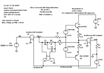
For reference, below is the simulation diagram of the circuit I used to compare feedback error correction (HEC) and feedforward error correction. The error in both cases is derived at the output of summer E3. Its input contains the frequency compensation necessary for proper operation of HEC. C2 represents the fact that the summer must have finite bandwidth. The derived error from E3 is either fed back (disabled in this schematic by gain of Summer E1 = 0), or fed forward to summer E2.
The output stage is built with ThermalTrak RET transistors with 0.22 RE and biased at a drop of 26 mV, for an idle current of 120 mA. The output stage is operated into a 4 ohms load at a voltage of 5 V peak at 1 kHz, near where crossover distortion is highest.
In subsequent posts I'll show some of the performance characteristics.
Cheers,
Bob
Attachments
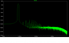
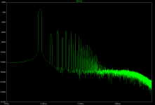
Here is the FFT spectrum when the same circuit is connected for feedforward error correction.
THD-1 reads 0.000064 %.
Note the startling similarity to the spectrum created when the circuit was using HEC. They are virtually the same. This blew me away.
Bob
THD-1 reads 0.000064 %.
Note the startling similarity to the spectrum created when the circuit was using HEC. They are virtually the same. This blew me away.
Bob
Attachments
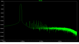
Here is the measured loop gain of the HEC circuit. The feedback loop was broken between the output stage output and the input to the E2 summer. A 100 Meg resistor in combination with the 1 k series resistor from the output stage (R4) provided DC stability and is what limits the loop gain to 100 dB at frequencies below 10 Hz.
This picture of loop gain illustrates the "feedback view" of HEC.
Bob
This picture of loop gain illustrates the "feedback view" of HEC.
Bob
Attachments
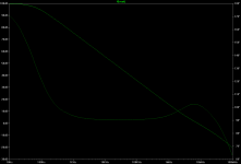
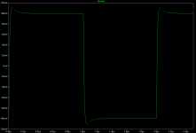
This graph shows the error-corrected frequency response of the output stage. 3 dB bandwidth is 22 MHz. Peaking is 0.4 dB. Curiously, this same peaking showed up in the frequency response of the feedforward stage, so it appears not to represent peaking due to the NFB process.
At 1 MHz, where one might cross over a global feedback loop around this stage in an amplifier, gain is +0.1 dB and phase lag is 0nly 0.8 degrees.
Bob
At 1 MHz, where one might cross over a global feedback loop around this stage in an amplifier, gain is +0.1 dB and phase lag is 0nly 0.8 degrees.
Bob
Attachments

Need to see a cleaner Spice simulation for the FFT (see attached). Have you got the FFT without any correction circuit?
What is your justification for slugging the FF? The whole point about FF vs FB is that FF not only cancels but needs no compensation whatsoever.
What is your justification for slugging the FF? The whole point about FF vs FB is that FF not only cancels but needs no compensation whatsoever.
Attachments
traderbam said:Rodolfo wrote in his paper:
While considering your table top and buying some more furniture polish, I've been reading your paper again. I really have a problem understanding how you came by the second of these two statements and I would like to understand the maths that led you to it.
In particular, the bit about "feeding back only the error" has me perplexed. What do you mean by "the error" and what node is it being fed to wrt Fig 3?
Thanks but by far it is not a paper, just a modest contribution to the forum.
What I call the error signal, is the difference between the main amplifier output and its input. The output is conveniently scaled down to match the input level, so what we have extracted at the output of S2 is esentially the amplifier introduced distortion, only referenced at the input signal level. Since this term has been introduced by the amplifier, is seems natural to call it error. It also seems intuitive that if this error is substracted now from the input, it could be ideally cancelled.
In contrast, regular negative feedback substracts a sample of the amplifier output from the input. This is not very intuitive as a means of correcting modifications introduced into the amplification process, but once the numbers are factored it turns out to be good, even perfect asimptoticaly with infinite gain. This last does turn to be intuitive for in the limiting case, an infinite forward gain implies the amplifier input must be null for the output to be bounded, which in turn means the output sample must be identical to the input.
Rodolfo
traderbam said:Need to see a cleaner Spice simulation for the FFT (see attached). Have you got the FFT without any correction circuit?
What is your justification for slugging the FF? The whole point about FF vs FB is that FF not only cancels but needs no compensation whatsoever.
Hi Brian,
The FFT of the uncorrected stage is shown below.
My FFT is perfectly fine, although I was lazy in letting the scale go all the way down to -270 dB, revealing trash that your FFT did't show as it cut off at 160 dB. We're not talking about who can plot better FFTs here, anyway.
Brian, I think you have lost sight of the reason that I presented this. What I was trying to show was that the HEC and feedforward have a lot in common when they are compered apples to apples - an amazing lot! That is why I applied the same error signal rolloff to both.
I was NOT trying to show that HEC is as good as pure, ideal, simulated EC. It is not, and I have said that before. Pure feedforward EC will win every time in a simulation like this. But that is academic, since the required output summer to do so is virtually impossible to realize in the real world without adding in quite a bit of distortion itself. I am surprized that point was lost on you.
The compensation I am using for the HEC is not "slugging" it, but it is on the conservative side. Again, I was not trying to gandstand and show how great HEC is, but rather to demonstrate its similarities in behavior to feedforward EC. The circuit I showed is actually quite stable down to much lower values of compensating capacitance.
Bob
Attachments
- Home
- Amplifiers
- Solid State
- Bob Cordell Interview: Error Correction