mikeks said:Where is Monahan University?
Can you post these notes?
analog_guy said:By all means, please post the material or give a complete citation so I can find it in a good library.
I got the material in hard copy only from a member here and don't know whether it is available online.
Rodolfo
PS What I may offer is a transcription focused on the most important aspects.
Far better to upload the scanned papers in their entirety and let folk make up their own minds as to what is relevant and what isn't.
mikeks said:.... let folk make up their own minds as to what is relevant and what isn't.
Absolutely agree Mike, but as said the material was mailed to me by another member, and it is not public domain as far as I know, will ask him about this.
I made the reference only to properly credit the original analysis, which on the other hand is basic and strightforward for anyone familiar with circuit theory.
Rodolfo
Re: Re: Re: Re: EC-based Amplifier Stability Question
The reason the whole document is important is the following is completely meaningless without further elucidation.
The reason the whole document is important is the following is completely meaningless without further elucidation.
ingrast said:.....a dual first order cascaded stage EC system behaves as a second order system with the natural frequency located approximately at the geometric mean of the stage's respective natural or cutoff frequency....
Rodolfo,
Monash University, after General Sir John Monash, WWI celebrated hero of Gallipoli.
Monash is in the southern suburbs of Melbourne.
Cheers,
Hugh
Monash University, after General Sir John Monash, WWI celebrated hero of Gallipoli.
Monash is in the southern suburbs of Melbourne.
Cheers,
Hugh
Hi all,
There was a lot of discussion in this thread on the relative merits of 'classical' negative feedback, error correction and various combinations of positive and negative feedback. A clear 'winner' didn't emerge, in large part (I think) because it is difficult to identify a single parameter to express those relative merits.
Mikeks and others have shown that many of the discussed topologies are in fact often to a large extend equivalent to each other, but does that mean that they have the same merit? Even if they are equivalent performance-wise, one may have advantages over the other in terms of designability and manufacturability.
One parameter that could be used to judge the relative merit is the sensitivity parameter, meaning how 'successful' a particular topology is to supress the impact of non-linearities in the open loop gain on the closed loop gain.
I have done some work on that, which is still very rudimentary, may have errors and maybe even be leading to a dead end, but I attach it nevertheless.
I would be gratefull for your thoughts about this.
Jan Didden
Attachments
Error Correction using a floating Correction Amplifier
I had mentioned this idea briefly in an earlier post, but have now had the time to simulate it.
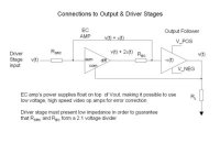
The idea is fairly simple: imagine that the power supplies for the correction amplifier are floated on top of the output voltage, v_out. Then the correction amp may be used to generate an accurate correction signal for both positive and negative output stages. Since the magnitude of the correction voltage is typically no more than a few volts, the correction amp need not generate a very large voltage swing.
For this application a video amplifier (EL2045 for example) works well. Consider such an amp that is configured with Rf = Ri, so its inverting gain is -1, then its non-inverting gain will be 1 + Rf/Ri = 2. Since its "ground" reference is v_out, Ri will be terminated to v_out also. Let us call the non-inverting input of the video amp as "sum", and its output "diff".
Referring to the attached figure, v(t) is the nondistorted input voltage that we also wish to appear into Rl, at the output of the follower stage. If we set Rsrc = Rec, then these two resistors form a 2:1 voltage divider. Assuming that the output stage introduces a subtractive error -e(t), then the corrected voltage going into the output follower must be v(t) + e(t). Since the video amp has a non invertaing gain of 2, the voltage appearing at its output is v(t) (the float voltage) + 2*e(t). Comparing the inputs to Rsrc and Rec, one can see that they share a common voltage term of v(t) plus a difference of 2*e(t). By picking off the voltage between Rsrc and Rec, it is easy to see that the resulting voltage is v(t) + e(t), which is exactly what needs to be driven into the output follower stage.
In order for this approach to work, it is important that the upstream stage driving v(t) provide a low impedance. This can be achieved by adding a low power follower stage to the VAS stage. We are guaranteed that the source driving Rec is a low impedance since it is being driven by the video op amp.
One final note: it will be necessary to put in a Vbe multiplier, or equivalent, at the beginning of the output follower stage to set the bias current correctly.
I am still in the process of simulating with both lateral MOSFETS and vertical MOSFETS. However, I have already seen error suppression in excess of 40 dB over the entire 20 - 20 KHz range. Furthermore, it is possible to achieve substantial corrections all the way up to 100 KHz. The EL045 video amp is particularly good in this respect, since its in-out propagation time is ~ 2.5 ns.
I had mentioned this idea briefly in an earlier post, but have now had the time to simulate it.
The idea is fairly simple: imagine that the power supplies for the correction amplifier are floated on top of the output voltage, v_out. Then the correction amp may be used to generate an accurate correction signal for both positive and negative output stages. Since the magnitude of the correction voltage is typically no more than a few volts, the correction amp need not generate a very large voltage swing.
For this application a video amplifier (EL2045 for example) works well. Consider such an amp that is configured with Rf = Ri, so its inverting gain is -1, then its non-inverting gain will be 1 + Rf/Ri = 2. Since its "ground" reference is v_out, Ri will be terminated to v_out also. Let us call the non-inverting input of the video amp as "sum", and its output "diff".
Referring to the attached figure, v(t) is the nondistorted input voltage that we also wish to appear into Rl, at the output of the follower stage. If we set Rsrc = Rec, then these two resistors form a 2:1 voltage divider. Assuming that the output stage introduces a subtractive error -e(t), then the corrected voltage going into the output follower must be v(t) + e(t). Since the video amp has a non invertaing gain of 2, the voltage appearing at its output is v(t) (the float voltage) + 2*e(t). Comparing the inputs to Rsrc and Rec, one can see that they share a common voltage term of v(t) plus a difference of 2*e(t). By picking off the voltage between Rsrc and Rec, it is easy to see that the resulting voltage is v(t) + e(t), which is exactly what needs to be driven into the output follower stage.
In order for this approach to work, it is important that the upstream stage driving v(t) provide a low impedance. This can be achieved by adding a low power follower stage to the VAS stage. We are guaranteed that the source driving Rec is a low impedance since it is being driven by the video op amp.
One final note: it will be necessary to put in a Vbe multiplier, or equivalent, at the beginning of the output follower stage to set the bias current correctly.
I am still in the process of simulating with both lateral MOSFETS and vertical MOSFETS. However, I have already seen error suppression in excess of 40 dB over the entire 20 - 20 KHz range. Furthermore, it is possible to achieve substantial corrections all the way up to 100 KHz. The EL045 video amp is particularly good in this respect, since its in-out propagation time is ~ 2.5 ns.
Attachments
janneman said:....Even if they are equivalent performance-wise, one may have advantages over the other in terms of designability and manufacturability....
Precisely the parameters I have spent many sleepless nights on; it was well worthwhile

Jan
I do not dare to criticise, but from your calculations of transfer functions it seems that such error correction (or as you call it positive feedback) all poles are in left half plane, so stable whatever happens.
From my very little experience with such circuits stability is complex, strange and unituitional area...
Have you done any calculations on what happens when more that one inertia effect exists in both A and G ?
regards
Adam
darkfenriz said:Jan
I do not dare to criticise, but from your calculations of transfer functions it seems that such error correction (or as you call it positive feedback) all poles are in left half plane, so stable ......
True.

darkfenriz said:Jan
I do not dare to criticise, but from your calculations of transfer functions it seems that such error correction (or as you call it positive feedback) all poles are in left half plane, so stable whatever happens.
From my very little experience with such circuits stability is complex, strange and unituitional area...
Have you done any calculations on what happens when more that one inertia effect exists in both A and G ?
regards
Adam
Hi Adam,
No, I have not done any calculations on more complex forms of A and G. Having had no formal engineering training, my progress here is slow; I learn in small steps.
That said, I have done some experiments with real life circuits along the Fig 2 in the paper, and have had no stability problems. In fact, my experience was that if you increase G beyond what is needed for the balance condition, going through the distortion null, the distortion increases again but with opposite phase. In this condition, however, the amp was still stable.
But my purpose was not to reopen this part of the discussion but rather to see if anyone believes that looking at sensitivity would be a good way to judge these types of circuits, rather than going around and around by converting one topology into an equivalent other and based on that stating that they are the same (although that exercise itself gains you valuable insight, of course).
Jan Didden
darkfenriz said:.... it seems that such error correction (or as you call it positive feedback) all poles are in left half plane, so stable whatever happens.
....
Adam,
This does not tell the whole story at least for a couple of reasons that come quickly to mind.
1. Left plane poles near the imaginary axis lead to humps in the frequency response which translate into ringing. We seek to minimize or supress ringing through increased phase margin, something we verify usually with square wave tests. Ringing per se should not be a problem if confined to ultrasonic frequencies, the caveat being their presence if significant may imply excursions into very nonlinear operating regimes with subsequent very audible IM products.
2. From the usability standpoint, manufacturing process variations, component aging, environmental temperature and supply variations, and different load conditions may shift those marginal poles to the right bringing parasitic oscillations.
EC can be analyzed as GNF and as such all the usual stability issues remain in place for each particular implementation.
On the other hand, it is valuable to keep the distinctive label in the sense both of the error handling conception, and the implementations possibilities which open different strategies in comparison with high OL gain only.
Rodolfo
Error Correction Simulation Results
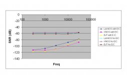
This weekend I had the opportunity to simulate three different output configurations with the video opamp error correction circuit described in a previous thread. These output configurations included IRF MOSFETS (IRFP240/IRFP9240), Lateral MOSFETs (BUZ901D/BUZ906D), and BJT devices (MJ15024/MJ15025)..
The drive voltage was generated from an ideal voltage source at 100VPP at different frequencies. The voltage rails for the output devices were +/- 65V. Adjustable DC sources were used to set the output stage quiescent idle current to 60 ma. Distortion was measured for input frequencies of 300 Hz, 1KHz, 3 KHz, 10 KHz, and 30 KHz. Since I don't have a script to calculate THD, I noted the largest harmonic (usually the 3rd).
Without error correction, all three output stages presented similar distortion characteristics over 300 Hz - 30 KHz of abut -60 dB. It should be noted that the BJT output pair was driven with a MOSFET follower because this EC circuit does not work well when driving a low impedance load.
With error correction enabled, the SNR increased substantialy for all three output stages, starting at aprox 55 dB improvement at 300 Hz, and decreasing to approx 20-25 dB at 30 KHz. Interestingly, there was not that much difference in either the uncorrected SNR or the degree by which error correction improved the SNR for the three output stages. I did notice that the error correction improvement got better if I decreased the output impedance of the driving source, something that would be expected for MOSFETS.
Draw your own conclusions...
Attachments
ingrast said:
Adam,
This does not tell the whole story at least for a couple of reasons that come quickly to mind.
1. Left plane poles near the imaginary axis lead to humps in the frequency response which translate into ringing. We seek to minimize or supress ringing through increased phase margin, something we verify usually with square wave tests. Ringing per se should not be a problem if confined to ultrasonic frequencies, the caveat being their presence if significant may imply excursions into very nonlinear operating regimes with subsequent very audible IM products.
2. From the usability standpoint, manufacturing process variations, component aging, environmental temperature and supply variations, and different load conditions may shift those marginal poles to the right bringing parasitic oscillations.
EC can be analyzed as GNF and as such all the usual stability issues remain in place for each particular implementation.
On the other hand, it is valuable to keep the distinctive label in the sense both of the error handling conception, and the implementations possibilities which open different strategies in comparison with high OL gain only.
Rodolfo
All very well-stated.
Bob
Re: Error Correction Simulation Results
Nice work. Although I did my EC in the context of MOSFETs to fight off the transconductance droop issue, I have always believed that EC was good for bipolars as well, especially in that it can virtually eliminate any gm-doubling effects that may result from heavier biasing into Class AAB.
Bob
analog_guy said:This weekend I had the opportunity to simulate three different output configurations with the video opamp error correction circuit described in a previous thread. These output configurations included IRF MOSFETS (IRFP240/IRFP9240), Lateral MOSFETs (BUZ901D/BUZ906D), and BJT devices (MJ15024/MJ15025)..
The drive voltage was generated from an ideal voltage source at 100VPP at different frequencies. The voltage rails for the output devices were +/- 65V. Adjustable DC sources were used to set the output stage quiescent idle current to 60 ma. Distortion was measured for input frequencies of 300 Hz, 1KHz, 3 KHz, 10 KHz, and 30 KHz. Since I don't have a script to calculate THD, I noted the largest harmonic (usually the 3rd).
Without error correction, all three output stages presented similar distortion characteristics over 300 Hz - 30 KHz of abut -60 dB. It should be noted that the BJT output pair was driven with a MOSFET follower because this EC circuit does not work well when driving a low impedance load.
With error correction enabled, the SNR increased substantialy for all three output stages, starting at aprox 55 dB improvement at 300 Hz, and decreasing to approx 20-25 dB at 30 KHz. Interestingly, there was not that much difference in either the uncorrected SNR or the degree by which error correction improved the SNR for the three output stages. I did notice that the error correction improvement got better if I decreased the output impedance of the driving source, something that would be expected for MOSFETS.
Draw your own conclusions...
Nice work. Although I did my EC in the context of MOSFETs to fight off the transconductance droop issue, I have always believed that EC was good for bipolars as well, especially in that it can virtually eliminate any gm-doubling effects that may result from heavier biasing into Class AAB.
Bob
Capacitive load effect on HEC
Thinking about the discussion on coils on another thread, has anyone here checked a prototype or done a SPICE simulation to assess the potential destabilizing effect a non-coil-isolated load capacitance will have on an output stage with error correction?
I have not, as I have always had at least 0.5 uH and 0.5 ohm isolating my EC output stage from the outside world.
Thanks,
Bob
Re: Capacitive load effect on HEC
Last week I picked up a copy of Ogata's "Modern Control Engineering", which goes into great length (900+ pages of length) on control and feedback theory. I want to see it makes sense to attempt to derive analytical expressions, vs. to rely upon empirical methods -- such as step response -- for multi-pole feedback systems.
I have simulated my EC amp design with and without output isolation inductors, but the tool I am using (Agilent's ADS) has known non-causality bugs of its own that may be introducing instablity unrelated to the actual circuit. Agilent is offering an upgraded version for the cost of Porsche Boxster. (I'd rather have the car). So I'll try simulating with HSPICE to see if the same tool-related stability problems recur.
Bob Cordell said:Thinking about the discussion on coils on another thread, has anyone here checked a prototype or done a SPICE simulation to assess the potential destabilizing effect a non-coil-isolated load capacitance will have on an output stage with error correction?
I have not, as I have always had at least 0.5 uH and 0.5 ohm isolating my EC output stage from the outside world.
Thanks,
Bob
Last week I picked up a copy of Ogata's "Modern Control Engineering", which goes into great length (900+ pages of length) on control and feedback theory. I want to see it makes sense to attempt to derive analytical expressions, vs. to rely upon empirical methods -- such as step response -- for multi-pole feedback systems.
I have simulated my EC amp design with and without output isolation inductors, but the tool I am using (Agilent's ADS) has known non-causality bugs of its own that may be introducing instablity unrelated to the actual circuit. Agilent is offering an upgraded version for the cost of Porsche Boxster. (I'd rather have the car). So I'll try simulating with HSPICE to see if the same tool-related stability problems recur.
Re: Capacitive load effect on HEC
Hi Bob,
Here's an LTSpice sim of your output stage back from the discussions in this thread in November of last year. One of the sims has a loop gain probe, so you just do an AC analysis and paste in the plot expression from the comment field to get the loop gain.
Bob Cordell said:Thinking about the discussion on coils on another thread, has anyone here checked a prototype or done a SPICE simulation to assess the potential destabilizing effect a non-coil-isolated load capacitance will have on an output stage with error correction?
Hi Bob,
Here's an LTSpice sim of your output stage back from the discussions in this thread in November of last year. One of the sims has a loop gain probe, so you just do an AC analysis and paste in the plot expression from the comment field to get the loop gain.
Attachments
- Home
- Amplifiers
- Solid State
- Bob Cordell Interview: Error Correction