Looks like Q3 and Q4 are designed to switch on and off so that preventing output transistors from switching ... similar to your patent.
I still do not see Hawksford in it, but I may be wrong.
All in all I found myself more comfortable looking at beginners' version of schematic...
I still do not see Hawksford in it, but I may be wrong.
All in all I found myself more comfortable looking at beginners' version of schematic...
Where I see the relation of Hawksford is that what you might
view as the bias circuit varies its voltage so that the output
voltage of the amplifier more closely resembles the input
voltage driving the output stage. In that regard, all these circuits
have a common element.
😎
view as the bias circuit varies its voltage so that the output
voltage of the amplifier more closely resembles the input
voltage driving the output stage. In that regard, all these circuits
have a common element.
😎
Yup, definitely.
This one from JVC seems to me just more about dynamic biasing than correction.
Circuits may be similar, but theory behind them may be not 🙂
This one from JVC seems to me just more about dynamic biasing than correction.
Circuits may be similar, but theory behind them may be not 🙂
It's in the details. If you build a circuit which keeps the
input voltage literally equal to the output, you can
retain bias on the unused half of the output stage so that
it doesn't shut off.
(Correct me if I'm wrong, Bob...)
😎
input voltage literally equal to the output, you can
retain bias on the unused half of the output stage so that
it doesn't shut off.
(Correct me if I'm wrong, Bob...)
😎
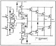
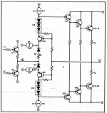
From the simplified version in post#1922 it seems the basic is the same, the EC center are Q7-Q8 with output node connected to their bases, and input signal from front end is feeded to their emitors (via Q3-Q4)
But why is that Q5-Q6 CCS' (7mA) are placed like that, the current path is in opposition with Q11-Q12' (4mA) current path?
But why is that Q5-Q6 CCS' (7mA) are placed like that, the current path is in opposition with Q11-Q12' (4mA) current path?
lumanauw said:But why is that Q5-Q6 CCS' (7mA) are placed like that, the current path is in opposition with Q11-Q12' (4mA) current path?
I believe they are making an effort to bias Q7 and Q8, there
being insufficient voltage across their bases to put them into
conduction. As a concept you could imagine removing the
current sources Q6 and Q6 and replacing the diodes with a
battery (with the + pointed toward the emitter of Q8).
😎
Nelson Pass said:It's in the details. If you build a circuit which keeps the
input voltage literally equal to the output, you can
retain bias on the unused half of the output stage so that
it doesn't shut off.
(Correct me if I'm wrong, Bob...)
😎
Hi Nelson,
That may sometimes be the case, but in the case of the Hawksford circuit I use driving a Class AB output stage, one side does go well off.
I look at these various techniques as being in two categories, although I suppose some could be in both. In the first category, the amount of bias spreading is modulated with signal voltage and or current. The LT1166 falls in this category, and it tends to prevent the off transistor from going all the way off. This might be thought of as a common mode effect, if the common mode is seen as the amount of bias spreader voltage.
In the second category, the circuitry alters the signal voltage, rather than the bias spreading voltage. This might be loosely thought of as a differential mode effect if the signal is thought of as differential mode (I know the semantics here could get really confusing). The Hawksfor circuit falls into this category. It does not need to alter the bias spread in order to do its job.
Of course, some circuit may operated to some extent in both of these modes.
Cheers,
Bob
I still don't get it, Mr. Pass. Usually emitor of Q7 (NPN) is more positive than emitor of Q8 (PNP).I believe they are making an effort to bias Q7 and Q8, there
being insufficient voltage across their bases to put them into
conduction. As a concept you could imagine removing the
current sources Q6 and Q6 and replacing the diodes with a
battery (with the + pointed toward the emitter of Q8).
The "battery" POV indeed makes me view the simplified CCT easier. This will make emitor of Q8 more positive than emitor of Q7. Are they trying to make Q7-Q8 active while having VbaseQ7=VbaseQ8?
lumanauw said:Q7. Are they trying to make Q7-Q8 active while having VbaseQ7=VbaseQ8?
Offhand I assume that there is some forward bias across the
bases, just not enough for the desired conduction.
😎
EC-based Amplifier Stability Question
Bob,
Just for fun I simulated a simple EC-based amplifier consisting of a front end voltage gain stage and an EC circuit consisting of a difference amp and a summing amp. In all cases I used a modified HSPICE version of the OPA637 opamp. The only change I made was to increase the voltage rails to +/- 65V. I know that this does not represent a real device, but I wanted to see how the circuit would behave at high power, and the OPA637 model doesn't care if the rail voltage is increased.
The output circuit consisted of four paralled BUZ901D/906D lateral mosfets. This output stage can readily source and sink over 50 amps. The idle current was set at approx 250 ma.
I simulated both with and without error correction, and there was about a 40 dB difference. Attached is a spectral distortion plot for the case with EC enabled. While simulations must be taken with a grain of salt, the trend is clearly in the correct direction.
One big question: has anyone worked out the stability criteria for an EC circuit? If found that injecting any high frequency signal greater than the the reciprocal of the loop response time resulted in runaway oscillation. If the EC circuit was removed the oscillation did not occur. Furthermore, the oscillation occurred even when the feedback path from the output to the input opamp was broken, so the problem must be in the EC circuit itself. The frequency of oscillation was on the order of 100 MHz. Maybe I should use the OPA627 for the EC stages, since it is spec'ed down to unity gain, and the OPA637 is not. However, the min gain for these devices is specified with no other active components in the signal path.
Given that an EC circuit implements a gain of unity, I am surprised that it would oscillate at all. My understanding of the gain/phase relationship is that Av must be >1 for oscillation to occur.
Attachments
Re: EC-based Amplifier Stability Question
Hi. First, congrats on such a big error correction. There is quite a bit of discussion earlier in this thread on EC stability issues, but I don't recall if a simply-stated stability criterion came out of it. Keep in mind that just because the total function seeks to achieve unity signal gain does not necessarily mean that it will behave as a simple unity-gain stage stability-wise. In one view of the EC stage, it is a negative feedback system that encloses a forward path whose gain is made theoretically infinite by unity positive feedback around that inner stage. This allows one to see that there is indeed a need for explicit compensation of the EC circuit. The circuit works well with high-speed discrete circuit implementation, but may be a bit more difficult to predict when implemented with op amps.
Cheers,
Bob
analog_guy said:Bob,
Just for fun I simulated a simple EC-based amplifier consisting of a front end voltage gain stage and an EC circuit consisting of a difference amp and a summing amp. In all cases I used a modified HSPICE version of the OPA637 opamp. The only change I made was to increase the voltage rails to +/- 65V. I know that this does not represent a real device, but I wanted to see how the circuit would behave at high power, and the OPA637 model doesn't care if the rail voltage is increased.
The output circuit consisted of four paralled BUZ901D/906D lateral mosfets. This output stage can readily source and sink over 50 amps. The idle current was set at approx 250 ma.
I simulated both with and without error correction, and there was about a 40 dB difference. Attached is a spectral distortion plot for the case with EC enabled. While simulations must be taken with a grain of salt, the trend is clearly in the correct direction.
One big question: has anyone worked out the stability criteria for an EC circuit? If found that injecting any high frequency signal greater than the the reciprocal of the loop response time resulted in runaway oscillation. If the EC circuit was removed the oscillation did not occur. Furthermore, the oscillation occurred even when the feedback path from the output to the input opamp was broken, so the problem must be in the EC circuit itself. The frequency of oscillation was on the order of 100 MHz. Maybe I should use the OPA627 for the EC stages, since it is spec'ed down to unity gain, and the OPA637 is not. However, the min gain for these devices is specified with no other active components in the signal path.
Given that an EC circuit implements a gain of unity, I am surprised that it would oscillate at all. My understanding of the gain/phase relationship is that Av must be >1 for oscillation to occur.
Hi. First, congrats on such a big error correction. There is quite a bit of discussion earlier in this thread on EC stability issues, but I don't recall if a simply-stated stability criterion came out of it. Keep in mind that just because the total function seeks to achieve unity signal gain does not necessarily mean that it will behave as a simple unity-gain stage stability-wise. In one view of the EC stage, it is a negative feedback system that encloses a forward path whose gain is made theoretically infinite by unity positive feedback around that inner stage. This allows one to see that there is indeed a need for explicit compensation of the EC circuit. The circuit works well with high-speed discrete circuit implementation, but may be a bit more difficult to predict when implemented with op amps.
Cheers,
Bob
Re: Re: EC-based Amplifier Stability Question
http://www.diyaudio.com/forums/showthread.php?postid=1126534#post1126534
Bob Cordell said:There is quite a bit of discussion earlier in this thread on EC stability issues, but I don't recall if a simply-stated stability criterion came out of it.
http://www.diyaudio.com/forums/showthread.php?postid=1126534#post1126534
Re: Re: EC-based Amplifier Stability Question
I think I have a handle on the stability problem. It turns out that opamps, even high speed ones like the OPA637, are not really that fast. Not only that, but this type of opamp has relatively poor drive capability. Both of these phenomena have the effect of adding delay in the feedback loop. If the opamp models are replaced by ideal gain stages (easy to do in HSPICE) then the stability problems go away.
It may make sense to consider the so called video opamps. These devices have a relatively low open loop gain, are very fast (tpd < 2.5 ns), and they can drive capacitive loads down to an equivalent of 100 ohms or less. Their voltage swing is quite small (+/- 10 V), but since the error correction voltage is also small, that should not be a problem. The approach I am investigaing is to float the video amp's +/- 15V supply on top of the power amp's output voltage. Then the voltage difference between two sides of the output stage can be measured without having to deal with a large common mode voltage.
I'll see how the simulations turn out. I'll also simulate in the frequency domain to look at the gain/phase relationship.
Jeff
Bob Cordell said:
Hi. First, congrats on such a big error correction. There is quite a bit of discussion earlier in this thread on EC stability issues, but I don't recall if a simply-stated stability criterion came out of it. Keep in mind that just because the total function seeks to achieve unity signal gain does not necessarily mean that it will behave as a simple unity-gain stage stability-wise. In one view of the EC stage, it is a negative feedback system that encloses a forward path whose gain is made theoretically infinite by unity positive feedback around that inner stage. This allows one to see that there is indeed a need for explicit compensation of the EC circuit. The circuit works well with high-speed discrete circuit implementation, but may be a bit more difficult to predict when implemented with op amps.
Cheers,
Bob
I think I have a handle on the stability problem. It turns out that opamps, even high speed ones like the OPA637, are not really that fast. Not only that, but this type of opamp has relatively poor drive capability. Both of these phenomena have the effect of adding delay in the feedback loop. If the opamp models are replaced by ideal gain stages (easy to do in HSPICE) then the stability problems go away.
It may make sense to consider the so called video opamps. These devices have a relatively low open loop gain, are very fast (tpd < 2.5 ns), and they can drive capacitive loads down to an equivalent of 100 ohms or less. Their voltage swing is quite small (+/- 10 V), but since the error correction voltage is also small, that should not be a problem. The approach I am investigaing is to float the video amp's +/- 15V supply on top of the power amp's output voltage. Then the voltage difference between two sides of the output stage can be measured without having to deal with a large common mode voltage.
I'll see how the simulations turn out. I'll also simulate in the frequency domain to look at the gain/phase relationship.
Jeff
Re: Re: Re: EC-based Amplifier Stability Question
Jeff:
What you have done in the simulation is to supress at least one pole in the forward path. This cannot be done in practice, no matter how wideband the OpAmp you choose.
It can be shown (Ed.Cherry, Monahan Univ. course notes) a dual first order cascaded stage EC system behaves as a second order system with the natural frequency located approximately at the geometric mean of the stage's respective natural or cutoff frequency. Damping is usually low, but the situation is not worse than with a regular GNF system with high OL gain, for in this case there are of necessity several forward transfer poles to deal with.
Rodolfo
analog_guy said:
.... If the opamp models are replaced by ideal gain stages (easy to do in HSPICE) then the stability problems go away.
....
Jeff:
What you have done in the simulation is to supress at least one pole in the forward path. This cannot be done in practice, no matter how wideband the OpAmp you choose.
It can be shown (Ed.Cherry, Monahan Univ. course notes) a dual first order cascaded stage EC system behaves as a second order system with the natural frequency located approximately at the geometric mean of the stage's respective natural or cutoff frequency. Damping is usually low, but the situation is not worse than with a regular GNF system with high OL gain, for in this case there are of necessity several forward transfer poles to deal with.
Rodolfo
Re: Re: Re: Re: EC-based Amplifier Stability Question
By all means, please post the material or give a complete citation so I can find it in a good library.
Regards
ingrast said:
Jeff:
What you have done in the simulation is to supress at least one pole in the forward path. This cannot be done in practice, no matter how wideband the OpAmp you choose.
It can be shown (Ed.Cherry, Monahan Univ. course notes) a dual first order cascaded stage EC system behaves as a second order system with the natural frequency located approximately at the geometric mean of the stage's respective natural or cutoff frequency. Damping is usually low, but the situation is not worse than with a regular GNF system with high OL gain, for in this case there are of necessity several forward transfer poles to deal with.
Rodolfo
By all means, please post the material or give a complete citation so I can find it in a good library.
Regards
Re: Re: Re: EC-based Amplifier Stability Question
Actually, op amp speed is of little moment considering that if used in an EC loop the op amps will or should operate with unity gain.
This has been covered to death in earlier posts.
analog_guy said:I think I have a handle on the stability problem. It turns out that opamps, even high speed ones like the OPA637, are not really that fast.
Actually, op amp speed is of little moment considering that if used in an EC loop the op amps will or should operate with unity gain.
This has been covered to death in earlier posts.
- Home
- Amplifiers
- Solid State
- Bob Cordell Interview: Error Correction