TOINO said:Just a small curiosity
TOINO,
worse, it was Tandberg's first MOSFET (Hitachi) power amplifier.
mikeks said:
On the contrary, because it relies on resistively loading down the transimpedance stage for correct operation, this is a sub-optimal implementation.
You're right, Mike; I was just being kind, I guess 🙂.
Bob
TOINO said:Just a small curiosity:
Believing in this information here http://www.nrhf.no/t-TPA-3006A.html the amplifier is from 1984 which is the publication year of Mr. Cordell paper on AES http://www.cordellaudio.com/poweramp/mosfet.shtml 😉
Actually, my amplifier was first presented at the Convention of the AES in 1982, with a preprint that fully disclosed the design details. I guess Tandberg liked it, but not enough to copy it optimally.
Cheers,
Bob
Electronics World Article.
Has anybody got a clean scan of the following Electronics World article?
"Error feedback in audio power"
By William de Bruyn
June 1997, p476
Has anybody got a clean scan of the following Electronics World article?
"Error feedback in audio power"
By William de Bruyn
June 1997, p476
Mikeks,
"Error feedback in audio power"
By William de Bruyn
June 1997, p476
I do have the article. Just allow me some days to scan it.
I sent you an email on saturday to get your email box address, I do not have it anymore.
"Error feedback in audio power"
By William de Bruyn
June 1997, p476
I do have the article. Just allow me some days to scan it.
I sent you an email on saturday to get your email box address, I do not have it anymore.
forr said:Mikeks,
"Error feedback in audio power"
By William de Bruyn
June 1997, p476
I do have the article. Just allow me some days to scan it.
I sent you an email on saturday to get your email box address, I do not have it anymore.
Sounds like an interesting article. Could you email it to me as well at bob@cordellaudio.com?
Thanks,
Bob
I need something to read on the bus...so kindly send it to me as well: bdt+diyaudio_AT_shaw_DOT_ca
Hi Mike,
---You've got my e-mail address.---
There were problems with the changing of the computer and transfering the data. I now have your email address again.
Bob Cordell
---Sounds like an interesting article. Could you email it to me as well at bob@cordellaudio.com?---
Yes, of course.
I will scan the article tomorow.
Regards.
Received!
Thanks Forr...
Actually, De Bruyn is wrong to suppose Tandberg's 3009A uses error feedfoward.
It is HEC in fact.
Thanks Forr...
Actually, De Bruyn is wrong to suppose Tandberg's 3009A uses error feedfoward.
It is HEC in fact.
Forr,
Any chance of getting a copy?
From what I remember it wasn't an article with EE's giving it a rigorous analysis. I think it showed Bob's amp.
I had it somewhere but lost it. EW's go AWOL from the company.
Thanks
Kevin
Any chance of getting a copy?
From what I remember it wasn't an article with EE's giving it a rigorous analysis. I think it showed Bob's amp.
I had it somewhere but lost it. EW's go AWOL from the company.
Thanks
Kevin
Fanuc said:Forr,
Any chance of getting a copy?
From what I remember it wasn't an article with EE's giving it a rigorous analysis. I think it showed Bob's amp.
I had it somewhere but lost it. EW's go AWOL from the company.
Thanks
Kevin
Oops! I forgot to include my email.
Kevin.dabson(@)gmail.com - Please remove the brackets ()
Kevin
Correction
Bob,
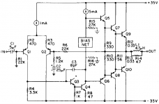
In respect of your ''back-of-envelope'' calculations here you state:
This is incorrect, as Q6 only stops conducting when the output swings beyond roughly 25V.
Given below is the corrected prose as i think it ought to have been:
I suggest running a DC Sweep of the circuit in question; this is less error-prone than ''back-of-envelope'' calculations.
Bob,
In respect of your ''back-of-envelope'' calculations here you state:
We now work our way forward through the bottom set of transistors. Q6 will be off with a reverse base-emitter bias of about 1.4V, since both ends of R10 are sitting at the output voltage level of +16.0.
This is incorrect, as Q6 only stops conducting when the output swings beyond roughly 25V.
Given below is the corrected prose as i think it ought to have been:
Assume that the amplifier delivers 2A into 8ohms placing the output at +16V.
Now work your way backward through the conducting path comprising the upper set of transistors. Resistor R12 drops 0.66V thereby placing +16.66V at Q9’s emitter.
Transistor Q9’s base is then at +17.26V with Q7’s base at +17.86V. Transistor Q5’s base is then roughly at +18.46V.
The bias network needed all along to have a fixed drop of about 3.6V. This means that the base of Q6 must be at about +14.86V.
We now work our way forward through the bottom set of transistors.
Transistor Q6’s emitter is then at +15.46V, while the top end of R10 sits at the output voltage level of +16.0V.
The base of Q8 is at about +15.46V also, and, ignoring insignificant base current, resistor R10 therefore passes 1.63mA.
Now, the top end of Q8’s emitter resistor, R11, is pulled to +17.26V by Q7, while Q8’s emitter is roughly at +16.06V. The voltage drop across R11 is 1.2V and, being 56ohms, therefore conducts about 21.4mA.
Thus, output transistor Q10 is off with a reverse base-emitter bias of about 0.06V, while all the drivers operate in Class A for the specified output of +16V.
Transistor Q6 only turns off when the output swings beyond +25V, while Q7/Q8 remain in Class A.
If, however, resistors R9/R10 are disconnected from the output rail and shorted together, then Q5/Q6 will also operate in Class A regardless of output voltage swing.
I suggest running a DC Sweep of the circuit in question; this is less error-prone than ''back-of-envelope'' calculations.
Attachments
Re: Correction
Good catch, Mike. You're right. I wrongly had it in my mind that the voltage on the base of Q8 was reverse biasing it instead of forward biasing it. I'm a big believer in both back of the envelope and simulation, as the former provides insight and teaching (when stupid mistakes like mine are not made) and the latter provides mindless precision (as long as the netlist is entered properly).
Bob
mikeks said:Bob,
In respect of your ''back-of-envelope'' calculations here you state:
This is incorrect, as Q6 only stops conducting when the output swings beyond roughly 25V.
Given below is the corrected prose as i think it ought to have been:
I suggest running a DC Sweep of the circuit in question; this is less error-prone than ''back-of-envelope'' calculations.
Good catch, Mike. You're right. I wrongly had it in my mind that the voltage on the base of Q8 was reverse biasing it instead of forward biasing it. I'm a big believer in both back of the envelope and simulation, as the former provides insight and teaching (when stupid mistakes like mine are not made) and the latter provides mindless precision (as long as the netlist is entered properly).
Bob
Re: Re: Correction
On the contrary, the purpose of SPICE is to provide rapid insight for the enlightened, otherwise your mistake might have gone undetected.
Bob Cordell said:
....... the latter provides mindless precision (as long as the netlist is entered properly).
Bob
On the contrary, the purpose of SPICE is to provide rapid insight for the enlightened, otherwise your mistake might have gone undetected.
Re: Re: Re: Correction
Actually, any idiot that can add could have picked up my stupid mistake 🙂
Bob
mikeks said:
On the contrary, the purpose of SPICE is to provide rapid insight for the enlightened, otherwise your mistake might have gone undetected.
Actually, any idiot that can add could have picked up my stupid mistake 🙂
Bob
Hey,
has anyone here ever build an amplifier using the error correction scheme shown in figure 4 of Hawksford's paper?
Here:
http://www.essex.ac.uk/ese/research/audio_lab/malcolmspubdocs/J3 Distortion correction%
It looks to me like the circuit could be improved by replacing T1 with a current mirror to mirror the collector current of T7 (and ditto for T4 and T8)
Cheers,
Glen
- Home
- Amplifiers
- Solid State
- Bob Cordell Interview: Error Correction