This one is from here
http://www.diyaudio.com/forums/showthread.php?postid=1141588#post1141588
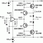
Q1+Q2+D1+D2 seems to form correction loop
http://www.diyaudio.com/forums/showthread.php?postid=1141588#post1141588
Q1+Q2+D1+D2 seems to form correction loop
Attachments
lumanauw said:This one is from here
http://www.diyaudio.com/forums/showthread.php?postid=1141588#post1141588
Q1+Q2+D1+D2 seems to form correction loop
Those devices form an interesting negative feedback loop. Matching among the diodes and the transistors is an issue for this interesting circuit.
Bob
lumanauw said:This one is from here
http://www.diyaudio.com/forums/showthread.php?postid=1141588#post1141588
Q1+Q2+D1+D2 seems to form correction loop
The output stage works in fact as a regular negative feedback loop, being the noninverting input at Q1-Q2 emitter junction and D1-D2 junction (output) the inverting input.
An interesting feature is the potentially large bandwidth (non inverting) resulting from Q1/Q2 working common base. Probably this circuit could benefit from an additional overall negative feedback loop, setting the inner OpAmp feedback so as to have a moderately high gain (10 - 100 times amplifier set gain).
Drawbacks are low output stage input impedance toghether with unity gain, which places severe drive requirements for the OpAmp.
As Bob noted, matching of D1-D2 V/I curve with Q1-Q2 Vbe/Ie curve may be tricky.
---Correction--- There is no possible match since Q1-Q2 Ie is basically constant while D1-D2 see the load current.
Rodolfo
I agree that this is a form of feedback loop.
Worse, it will have very low damping factor, because it senses output current and will have pretty high crossover distortion despite lateral mosfets and high idle current, IMHO.
Worse, it will have very low damping factor, because it senses output current and will have pretty high crossover distortion despite lateral mosfets and high idle current, IMHO.
This looks like a mini-CFA follower inside the overall op-amp loop. Those 1.5mA currents end up driving the MOSFET capacitances in one direction or other, could be a problem as a general purpose technique (ie. if the FETs have 1000pF of Cgs).
EDIT - Sorry just noticed the loop isn't closed around the whole thing - still have to slew those MOSFET gates.
EDIT - Sorry just noticed the loop isn't closed around the whole thing - still have to slew those MOSFET gates.
mikeks said:An interesting take on EC
I fail to see the interesting crumb, it looks like a 3d semester engineering school textbook on controll systems.
Must be me: too early, the coffee meter doesn't read 50% yet.
mikeks said:
Hi Mike,
It would be even more interesting if I could read Japanese!
Can you tell what the point is that he is trying to make?
Thanks,
Bob
Bob Cordell said:
Hi Mike,
It would be even more interesting if I could read Japanese!
Can you tell what the point is that he is trying to make?
Thanks,
Bob
Yes, Japanese would be good, but is not necessary for a fundamental appreciation of his points, some of which are rather misleading.
In essence he attempts to cover issues beaten to death, here, here and here, but in a much less intuitive fashion.
powerbecker said:I use only inverting amps for the summers, because they have for this purpose the smallest error...as models ..and in reality!
Heinz!
Heinz,
The inverting summers you've used here are not a good idea because U1 has to swing roughly twice the output voltage, making it the predominant source of intra-loop non-linearity.
Yes, but a gain other than unity reduces loop gain local to each op amp. Result? More distortion.
Solution? Use diff amps, or diff amp+summing inverter.
Solution? Use diff amps, or diff amp+summing inverter.
mikeks said:Yes, but a gain other than unity reduces loop gain local to each op amp. Result? More distortion.
Solution? Use diff amps, or diff amp+summing inverter.
Please demonstrate it, and dont´t forget to simulate the diff amp with realistic values and tolerances!

mikeks said:Nothing to do with EC.
Thats why I mentioned Transconductance! not EC
I am trying to find a schematic for a amp with error correction but with 4 pairs of output mosfets. I have plenty of spare laterals here.
I think there was a design from Tandberg that used error correction (european amp I think). Something like 8009A, 9008A ?? Think it was printed in Electronics and Wireless World.
I could just add more outputs to an existing design but it may go bang!. The loop stability of the EC output stage may be a problem.
- Home
- Amplifiers
- Solid State
- Bob Cordell Interview: Error Correction