gootee said:
.... I'm sorry to have brought it up without first doing some research.
.....
- Tom Gootee
Nobody can possibly be aware about everything that is going on, this is a splendid clearinhouse in this respect.
Rodolfo
mikeks said:Reducing K4 from 50 to unity (with the same misalignment of 10% in the gain of summer S1) causes THD to increase by a significant amount, to 0.17%.
Thus, although the magnitude of K4 has no effect at balance, when such an imbalance exists, then it desirable that K4 be made as large as possible to desensitize the loop to the error.
Indeed, increasing the gain of K4 to 1K reduced THD (with a misalignment of 10% in the gain of summer S1) to just 0.00035%.
These results seem to confirm Hawksford's findings, and, on this basis, the circuit modification above is recommended.
Nevertheless, whether these results are replicated in practice remains to be seen.
Discuss.
Mikeks,
I appreciate all of the work that you've done, on this. I have been trying to follow this part of the discussion, even though my knowledge of control theory and mathematics is a bit rusty. But, mainly, I have found it to be difficult to re-navigate the thread, well-enough, due to the number of messages involved, and also all of the links to previous posts, intervening and conflicting posts, corrections, repetitions, et al.
I don't like to be a bother. But, do you already have, or can you provide, a summary, or a single document, or, maybe easiest, a properly-sequenced list of links, that includes all of the really-relevant stuff, so far, "all in one place"? That would also make it much more accessible for everyone who tunes-in later.
If that's not practical or desirable, from your point of view, please feel free to just forget that I asked.
Thanks.
- Tom Gootee
Bob Cordell said:
Actually Tom, I've already built a test instrument similar to what you describe. It is called the Distortion Magnifier. I first used it to test my MOSFET power amplifier over 20 years ago. I described the technique briefly in my MOSFET amplifier AES paper.
A more up to date and detailed description of the Distortion Magnifier is provided on my website at www.cordellaudio.com. Just look under "Distortion & Distortion Measurement", then click on "Sensitive Distortion Measurement". I soon hope to have an even more detailed description of the DM on my site.
Cheers,
Bob
Howdy Bob,
Thanks for those pictures of the RMAF. I look foward to attending next year.
Do you have or intend to have any audio products for sale on-line?
Cheers.
Mike.
ingrast said:
Nobody can possibly be aware about everything that is going on, this is a splendid clearinhouse in this respect.
Rodolfo
Rodolfo,
You are right! But I also appreciate your kindness for having mentioned it.
- Tom Gootee
gootee said:.......can you provide, a summary, or a single document....
- Tom Gootee
I'll probably get around to doing this, though not immediately.
I've gone to great lengths to link each post to a preceding one in the interest of continuity; navigating your way through these links can't be that difficult, surely.
gootee said:
Heinz,
Thanks!
I could not resist trying to make it better:
To get a fast step response with no overshoot or ripple, and the same with 1 uF in parallel with the 8 Ohm load, I had to "cheat" and add a NFB loop (AC-coupled!).
Now, there is NO overshoot or ripple in the step response into 8 Ohms. And it's still _almost_ as good with 1 uF added (w/ESR .02). [Steps: 20v p-p output, from 1v p-p pulse input with 2.5 us edge times.]
It can be made more stable with >= 2 uF by increasing C22 to 560 pF or more, at the expense of a slight degradation of the step response when 1 uF or 1 pF is paralleled with the load. The THD-20 can be made lower, also, but probably only at the expense of the quality of the step responses, AFAIK (as far as I know).
THD is .000230%, for about 20v p-p into 8 Ohms (.000229% w/1uF). (Output amplitude was adjusted by changing input amplitude, to match the output amplitude of your ec_amp-hb2.asc circuit, for comparison.)
The EC-Amp-tg3.asc LT-Spice circuit is attached. Remove the ".txt" from the filename.
The circuit is a little troublesome, sometimes, for me, with LT-Spice, especially when using the pulse input. I would like to try, for example, lowering the resistances near the end of the ec loop (R26, R19, R20), or raise R30 to increase the ec loop's gain, but always get a "timestep too small" message from LT-Spice. Similarly, I cannot even lower the pulse input's amplitude without getting an "iteration limit reached" message, which I also get when trying to run an AC Analysis.
- Tom Gootee
Tom,
now I cannot improve it!
Thank you for your excellent work!
Regards
Heinz!
janneman said:
Well, in electronics like in real life, brute force often has the edge 😉 . But playing with ec is quite interesting. Notwithstanding the discussions here that it is equivalent to nfb, the character, if I can call it that, of an ec amp is definitely different from a nfb amp.
You really have to think differently, there is no longer the overriding concern to get very high gain. What strikes me is the almost complete adsense of oscillatory tendencies, ec circuits (at least in my experience) tend to be very docile.
If you are looking to something different from the tired old ways, ec amps are worth a try!
Jan Didden
Jan, there are many ways to Rome....I look always for the shortest (corresponding to my knowledge) 🙂
Till today I have never seen EC design which beats NFB.
The proof of the pudding can be, to improve a classD stage with it´s "nice" filter at the end. Here end the way for NFB....
I dont´t try it till now and I´m not all too optimistic.
For the same purpose I did some simulations with feedforward EC.
This works quite good but it ends always with a far to big correction amp... at that time I also missed a good idea!
Regards
Heinz!
mikeks said:Thanks for those pictures of the RMAF. I look foward to attending next year.Mike.
Me 2!
Jan Didden
mikeks said:
I'll probably get around to doing this, though not immediately.
I've gone to great lengths to link each post to a preceding one in the interest of continuity; navigating your way through these links can't be that difficult, surely.
Mike, indeed, your efforts to keep your posts consistent and the story continuous are great. Still a single document would be even greater - whenever you get the time!
Jan
powerbecker said:
Tom,
now I cannot improve it!
Thank you for your excellent work!
Regards
Heinz!
Heinz!,
Thanks so much for the encouraging words!
You are probably being way too kind. And I probably just got lucky, accidentally. But still, it's always great to hear some praise, especially since I have only been dabbling in electronic design for the last several years, and only seriously for the last two years, after doing no EE work at all for about 15 years, and knowing mostly only control theory and not too much about actual circuits, before that.
Thanks again! Back to the circuits...!
- Tom Gootee
Mikeks wrote:
The scheme you have described, Mike, is one where a new PFB loop is added to the original one so that if the gain generated by the original should decrease significantly (which it does when one of the summers does not have a gain of 1 - the infinite gain condition of your example circuit) then naturally having the extra PFB circuit will make up the difference. When the original has infinite gain the extra PFB doesn't add anything.
But the whole thing is a complete waste of transistors when you realise that the original PFB loop is redundant and can be replaced by a simple integrator that completely removes the dependence of the circuit on summer gain tolerance.
I stress once again that generating gain by means of a PFB loop MULTIPLIES the distortion of the components within that loop. Putting a PFB loop around the output stage, which is the source of the distortion one is trying to minimize, is counter productive.
For those of you who are new to control theory, please think about why Hawksford comes up with all these ideas. Think carefully about that.Nevertheless, whether these results are replicated in practice remains to be seen.
The scheme you have described, Mike, is one where a new PFB loop is added to the original one so that if the gain generated by the original should decrease significantly (which it does when one of the summers does not have a gain of 1 - the infinite gain condition of your example circuit) then naturally having the extra PFB circuit will make up the difference. When the original has infinite gain the extra PFB doesn't add anything.
But the whole thing is a complete waste of transistors when you realise that the original PFB loop is redundant and can be replaced by a simple integrator that completely removes the dependence of the circuit on summer gain tolerance.
I stress once again that generating gain by means of a PFB loop MULTIPLIES the distortion of the components within that loop. Putting a PFB loop around the output stage, which is the source of the distortion one is trying to minimize, is counter productive.
 Moderator's edit: The posts have been moved to the Studio amplifier thread
 traderbam said:Jan, are you joking again?
What do you mean by 'again' ? I am serious of course.
Jan Didden
powerbecker said:
Jan, there are many ways to Rome....I look always for the shortest (corresponding to my knowledge) 🙂
Till today I have never seen EC design which beats NFB.
The proof of the pudding can be, to improve a classD stage with it´s "nice" filter at the end. Here end the way for NFB....
I dont´t try it till now and I´m not all too optimistic.
For the same purpose I did some simulations with feedforward EC.
This works quite good but it ends always with a far to big correction amp... at that time I also missed a good idea!
Regards
Heinz!
Heinz!,
Don't give up on it, quite yet!
Comparing to my last posted circuit (EC_Amp-tg3.asc), but with a slightly-modified EC topology, it LOOKS like I have just found a simple way to decrease the ec amp gain by a factor of more than 10, while retaining the same THD level (and also improving the steps/stability), even when not using an input filter!
Alternatively, I can keep the ec amp gain the same but get about 1/2 the THD, and not change the step response.
Even better, it looks like this effect "should" be able to be further "scaled", so that the improvements above could be increased by larger factors, which is what I am trying, right now.
I am still investigating how far I can take it, et al, and hope to be able to provide details, soon.
- Tom Gootee
As shown here, making K4=1 reduces THD roughly by half for a 10% misalignment in the gain of S1.
This is consistent with Hawksford's averment that sensitivity to such is reduced by 1/(1+K4).
Indeed, his recommended connection of a resistor Rs between the output of the power stage to the input of the error-cancellation loop necessarily sets K4=1.
While desirable in principal, this is clearly inadequate in practice: what is required is some means to effect K4>>1.
Discuss.
Text changed by request of Mikeks, Dec,9,2006.
gootee said:
Heinz!,
Don't give up on it, quite yet!
Comparing to my last posted circuit (EC_Amp-tg3.asc), but with a slightly-modified EC topology, it LOOKS like I have just found a simple way to decrease the ec amp gain by a factor of more than 10, while retaining the same THD level (and also improving the steps/stability), even when not using an input filter!
Alternatively, I can keep the ec amp gain the same but get about 1/2 the THD, and not change the step response.
Even better, it looks like this effect "should" be able to be further "scaled", so that the improvements above could be increased by larger factors, which is what I am trying, right now.
I am still investigating how far I can take it, et al, and hope to be able to provide details, soon.
- Tom Gootee
Hello Tom,
I never give up! 🙂
But there are some little things to :
Revenue waits for my monthly vat declaration
 , my client wait for the specs from the next to last project, I had to check the layout from my own current work, I had to design a simple 500kHz 5kV source, friends are waiting for a call and..... and what do I :
Sitting in front of PC and check out my last idea!! 😀
Tom keep on, I´m curious about your results!
Regards
Heinz!
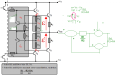
Hi Mikeks! Below picture says my thought. What do you think of it ?
Can we calculate distortion of T1 ?
I tried to simulate Error Correction schematic. Sim show that distortion still quite hight. Is THD of EC still high ? Are You, tradebarm, AndyC, powerbecker, gootee trying optimize more EC ?
thanks!
Can we calculate distortion of T1 ?
I tried to simulate Error Correction schematic. Sim show that distortion still quite hight. Is THD of EC still high ? Are You, tradebarm, AndyC, powerbecker, gootee trying optimize more EC ?
thanks!
Attachments
Hi, Thanh,
I think (not calculate 😀) that EC capability of this CCT is depended on T1 and T2. The EC will be limited by the nonlinearity of T1-T2 itself.
Can you simulate, for example put darlington for T1-T2, does it change anything?
Or put a trick, to make T1-T2 heavily biased (to get linear operation on T1-T2)?
- Home
- Amplifiers
- Solid State
- Bob Cordell Interview: Error Correction