http://www.freeweb.hu/clearvoice/images/integra1.jpg
Hi,
Etalon integra is designed by Sallai Laszlo - as I remember. One of is other design was the Alfa: http://www.freeweb.hu/clearvoice/images/alfa1.jpg
Regards,
Hi,
Etalon integra is designed by Sallai Laszlo - as I remember. One of is other design was the Alfa: http://www.freeweb.hu/clearvoice/images/alfa1.jpg
Regards,
Hi, Mikeks,
I try to use this value to HEC equation, and it seems 6k8 is not the "should be" value for R1. Too big.
This resistor is from VAS output to ground. It's not series resistor like in HEC.
Mikeks, will the HEC still works without R1 ?
R1=6K8
I try to use this value to HEC equation, and it seems 6k8 is not the "should be" value for R1. Too big.
This resistor is from VAS output to ground. It's not series resistor like in HEC.
Mikeks, will the HEC still works without R1 ?
Hi, EDL,
The Etalon Integra is not using global feedback. Is this amp low biased classAB or full classA? How many mA bias in final transistors? I try to figure out whether the CCT used in Integra is HEC or not.
What is the value of VR in bases and in emitors of BD139-BD140 (2 pots marked with "just")?
The Etalon Integra is not using global feedback. Is this amp low biased classAB or full classA? How many mA bias in final transistors? I try to figure out whether the CCT used in Integra is HEC or not.
What is the value of VR in bases and in emitors of BD139-BD140 (2 pots marked with "just")?
lumanauw said:Hi, Mikeks,
Mikeks, will the HEC still works without R1 ?
No.
If there is anything you didn't understand in this post, please feel free to ask.
If there is anything you didn't understand in this post, please feel free to ask.
So, the one in Etalon Integra is NOT Error Correction?
lumanauw said:Hi, Toino,
It really works? That's good news 😀
What is your impression of the sound before and after EC is implemented. Is it better sounding?
Hi lumanauw
I have made that modification some time ago. At the time I have made some simulations on pspice V8 before test the circuit in the amplifier.
I must search for the files in my hold backups and then I will post it here. Just give me some days…
The amplifier is not Hi-Fi. It is a 4 kilowatt beast for concert loudspeakers and I have never listened it with the EC.
But the THD was so low that the A1-Neutrik I have at the time could not measure it. (< 0.003%)
I remember that I have constructed a separated working prototype based on the simulations… mosfet drivers and bipolar output devices… will see the files when I found then.
Hi, Toino,
Traderbam found out that the modified EC (which is driven from the emitors of the VBE multiplier) is not working.
In here
http://www.diyaudio.com/forums/showthread.php?postid=1061815#post1061815
You measure (with Neutrik A1?) and it works to lower distortion ?
Traderbam found out that the modified EC (which is driven from the emitors of the VBE multiplier) is not working.
In here
http://www.diyaudio.com/forums/showthread.php?postid=1061815#post1061815
You measure (with Neutrik A1?) and it works to lower distortion ?
A thread about HawksfordEC
http://www.diyaudio.com/forums/showthread.php?s=&threadid=62595&highlight=
http://www.diyaudio.com/forums/showthread.php?s=&threadid=62595&highlight=
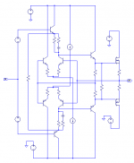
edl said:http://www.freeweb.hu/clearvoice/images/integra1.jpg
Hi,
Etalon integra is designed by Sallai Laszlo - as I remember. One of is other design was the Alfa: http://www.freeweb.hu/clearvoice/images/alfa1.jpg
Regards,
Viva Sallai Laszlo!
Good amps. Very good.
lumanauw said:Hi, Toino,
Traderbam found out that the modified EC (which is driven from the emitors of the VBE multiplier) is not working.
In here
http://www.diyaudio.com/forums/showthread.php?postid=1061815#post1061815
You measure (with Neutrik A1?) and it works to lower distortion ?
Lumanauw
Don’t worry about the circuit. Surely it works… just give me some time to search for the files.
Driving it from the emitters forms a kind of “current feedback” amplifier
Hi, Toino,
I'm glad to hear that 😀
In your modified schematic, you put 100ohm VR between output and input of EC transistors. How do you adjust it?
I'm glad to hear that 😀
In your modified schematic, you put 100ohm VR between output and input of EC transistors. How do you adjust it?
lumanauw said:Hi, EDL,
The Etalon Integra is not using global feedback. Is this amp low biased classAB or full classA? How many mA bias in final transistors? I try to figure out whether the CCT used in Integra is HEC or not.
What is the value of VR in bases and in emitors of BD139-BD140 (2 pots marked with "just")?
Etalon Integra-1 is HEC cct, output bias is ~300mA , VR on the bases is 20k, VR on the emitters of BD's is 10k.
lumanauw said:
So, the one in Etalon Integra is NOT Error Correction?
It is EXACTLY the same principal, although the implementation is somewhat compromised.
Untried and untested Yokoyama-Hawksford mods.
Hi Andy_C.
Continuing with our discussion from here, here and here.
Some obvious mods, the most notable of which is the increase in voltage efficiency, and the change of drivers to BJTs: i am generally uncomfortable with MOSFET drivers. 😉
Whether the whole thing makes sense in practice, or even SPICE, remains to be seen. 😀
Attachments
Hi Mike,
I've been working on a similar idea with a bjt output amplifier. Right down to the current sources. My error reference is right from the Vas. Still playing with it, but the technique is effective.
I've been delayed over a year. 😡 One day I'll get back to it. You guys are giving me a stronger urge to complete it.
-Chris
Hi Mike,
It's interesting. I get lost in the math of this and it comes right around to something I've put together. Cool! 😎 I did find that BJT outputs sounded better than mosfet types in my work, and not by a little bit either.
You now have my complete attention sir! Use small words so I can follow you. 😉
-Chris
anatech said:My error reference is right from the Vas.
-Chris
Not a good idea: this is a relatively high impedance node.
Hi Mike,
Yes, and my error detector is reasonably high impedance. The Vas has enough current so far.
I don't know that this would translate into an amplifier with 80 V rails though. I'm working around the 35 ~ 50 V mark now.
I built my correcton circuit on a small PCB. This is so I could move the connections around to test it. One day I swapped the inputs around by mistake. It took me a bit to figure out why the performance was worse! Stop laughing!
-Chris
- Home
- Amplifiers
- Solid State
- Bob Cordell Interview: Error Correction