anatech said:Hi Mike,
It's interesting. I get lost in the math of this and it comes right around to something I've put together. Cool! 😎 I did find that BJT outputs sounded better than mosfet types in my work, and not by a little bit either.
You now have my complete attention sir! Use small words so I can follow you. 😉
-Chris
It shouldn't be too difficult to follow, especially if you understand the reasoning here and here.
I find that the quickest way to understand a circuit is to analyse it on its own merits.
Going off at a tangent into high-brow theory before figuring out what the circuit is supposed to do and how it is supposed to do it is an heroic waste of time, in my modest opinion.

Hi Mike,
My problems right now are time and attention. I'm working on both.
I do understand things better when presented with a schematic and sometimes a small explaination. The math behind it loses me at times, and when you miss a little piece, you're done for! 😀
I did get a chance to hear the Marantz PM-17. It sounded pretty good, but you can't really tell from a quick listen.
-Chris
anatech said:I did get a chance to hear the Marantz PM-17. It sounded pretty good, but you can't really tell from a quick listen.
-Chris
Single pair of output devices: grossly inadequate for the supply rails used.
Hi Mike,
They didn't have it turned up. I haven't even looked at the schematic for it yet. I'm sure I will.
I'll say one thing. They sure are very pretty. WAF is extrememly high.
-Chris
They didn't have it turned up. I haven't even looked at the schematic for it yet. I'm sure I will.
I'll say one thing. They sure are very pretty. WAF is extrememly high.
-Chris
More speculation.
Continuing from here.
Since decreasing the EC loop's sensitivity to misalignment in the summers requires K4>>1, as established here, it has occurred to me that the desired increase in K4's gain may well be implemented by simple diff. amps, as roughly shown below.
Thoughts and suggestions anyone?
Continuing from here.
Since decreasing the EC loop's sensitivity to misalignment in the summers requires K4>>1, as established here, it has occurred to me that the desired increase in K4's gain may well be implemented by simple diff. amps, as roughly shown below.
Thoughts and suggestions anyone?
Attachments
I have found the files. 6 years hold... but now I have the problem of size.
Could some body teach me the way of post bigger size images, please?
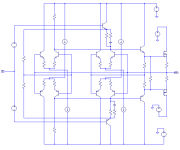
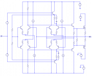
This one is the circuit kernel.
The diodes at the output are non linear loads and the V21 generator injects error signals through R129 directly on output to easily analyze the EC reaction.
Q1 and Q2 are also temperature sensors to bias compensation.
The node formed by the junction of R1/R2 is a low impedance input and is there that the null action takes place with R139//R30.
R139 is a fine adjust for the precise null.
This circuit works in real world ... I have made an amplifier with it. Just replace Mje3055/2955 by better ones and go.
One could replace Q68 Q69 driver by Mosfet, IGBT etc. EC compensates automatically the bias and whatever.
I like this topology because the power section is self-contained; it works alone…
Only thing we need to have the complete amplifier is replace V25 generator by a voltage amplifier with low output impedance.
It is easy to make a fast one with low THD.
Global feedback is a choice…
And this one is also a possibility: http://www.diyaudio.com/forums/showthread.php?postid=609507#post609507
Could some body teach me the way of post bigger size images, please?
This one is the circuit kernel.
The diodes at the output are non linear loads and the V21 generator injects error signals through R129 directly on output to easily analyze the EC reaction.
Q1 and Q2 are also temperature sensors to bias compensation.
The node formed by the junction of R1/R2 is a low impedance input and is there that the null action takes place with R139//R30.
R139 is a fine adjust for the precise null.
This circuit works in real world ... I have made an amplifier with it. Just replace Mje3055/2955 by better ones and go.
One could replace Q68 Q69 driver by Mosfet, IGBT etc. EC compensates automatically the bias and whatever.
I like this topology because the power section is self-contained; it works alone…
Only thing we need to have the complete amplifier is replace V25 generator by a voltage amplifier with low output impedance.
It is easy to make a fast one with low THD.
Global feedback is a choice…
And this one is also a possibility: http://www.diyaudio.com/forums/showthread.php?postid=609507#post609507
Attachments
This is the simulation result...
Green triangle is signal input (V(in)) and Red triangle is Output.
The null here is not perfect. Just a mater of better adjusts.
The other curves are internal signals that show the EC correction to the external error signal deliberately injected by V21.
Please note that V21 error signal only exists on the output. We see here the EC reaction to null that signall.
I have chose V21 signal with a frequency higher then the input signal for ease of clarification.
Attachments
To late Mikeks...
Please be a good boy and resimulate this stuff on your simulator.
I cannot reinstall that old simulator on my main machine.
Fortunately I have kept an old PC with win95 where the files are now but are a lot of work to show it here.
Will post a version of the voltage amplifier later…
Please be a good boy and resimulate this stuff on your simulator.
I cannot reinstall that old simulator on my main machine.
Fortunately I have kept an old PC with win95 where the files are now but are a lot of work to show it here.
Will post a version of the voltage amplifier later…
Actually, comparing this concept with the models here and here, it would appear i have assigned incorrect polarity to the "desensitizing'' cell.
Corrected arrangement below:
Corrected arrangement below:
Attachments
Well, why stop now? 😉
Since the value of |K4| becomes irrelevant at balance, then we might as well load the "desensitizing'' cells with current mirrors to ensure |K4|>>1.
Thoughts anyone?
Since the value of |K4| becomes irrelevant at balance, then we might as well load the "desensitizing'' cells with current mirrors to ensure |K4|>>1.
Thoughts anyone?
Attachments

Hi, Toino,
Interesting design indeed 😀
How does it sound?
In your final section, R22-R1 and R23-R2, are they for limiting the gain of Q1-Q3?
Is there any particular rule of thumb of how to determine the ratio of R13 towards R30/R139?
Interesting design indeed 😀
How does it sound?
In your final section, R22-R1 and R23-R2, are they for limiting the gain of Q1-Q3?
Is there any particular rule of thumb of how to determine the ratio of R13 towards R30/R139?
After reading my old notes, I have found the initial simulations made with opamps in an attempt to fully understand the circuit.
They are maybe interesting…
Topology is the same but with temp sense diodes on the input and opamps instead of transistors.
On the simulation result we see the input and output triangular waves V(in) V(OUT)
V(ERROR) is the spurious signal injected on output and is greater then the output signal itself.
On top in blue and down in yellow we have the mosfet gate signals.
Note the DC bias offset of gate signals and the EC correction.
Attachments

Lumanauw

Please revise the equivalent circuit made with opamps…and try to understand how it works.
Than revise the anterior transistor circuit and compare it… functionally they are the some.
Q1-Q3 are now diodes and are only temperature dependent level shifters. No voltage gain.
On practice they must be assembled in thermal contact with the output power devices.
Hi, Toino,
The opamp version makes things clearer 😀 The diodes are level shifters, and the opamp tries to maintain output=input, even there is very big forced error signal.
There is one question. Opamp are internally have very big gain (very big Error Correction capability).
Is this means putting opamp as the "center" of EC is preferable than just 1 or 2 transistors?

- Home
- Amplifiers
- Solid State
- Bob Cordell Interview: Error Correction