Bob Cordell said:
Yes, if look at it correctly, you can always find a positive feedback loop in the Hawksford EC scheme. Brian has been correctly pointing this out.
Bob
Hi Bob,
You see, the danger with block diagram manipulation in isolation, as i found out in control systems class many years ago, is that virtually ANY system can be represented by a myriad combinations of positive, negative and/or feedfoward entities, ALL, in the final analysis, with identical closed-loop transfer functions.
The first order ''descriptive'' block diagram is the key missed by many.
If you can show this positive feedback loop in your circuit, it would be most helpful.
mikeks said:Hi folks.
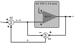
I am trying and failing to see any positive feedback here:
The output stage is approximately unity gain, shown in your diagram as exactly unity and non-inverting, thus there must be positive feedback since if one path to the subtractor is negative feedback the other path must be positive. The gain is slightly less than one in real life and therefore there would be more gain in the positive path.
On the other hand, if the system is trimmed so that the output of the subtractor is only distortion, then it seems that there is no "signal" being fed back, only the distortion correction term. Trimming is obviously never perfect and there are frequency dependencies to consider.
I dislike the term error correction, brings to mind ECC memory in computers and/or error correction codes in communication systems, and prefer perhaps a variation on predistortion.
It is interesting to view the distorted drive to the VAS or output stage as the predistortion required to correct those stages in systems that provide a low distortion output.
Pete B.
Ultima Thule said:Now it works... 🙂
I was not suggesting that there was anything wrong with the original diagram, just offered the positive feedback perspective. Seems to me you now have x+e at the output of S2 which is adding in the error term rather than subtracting it.
Pete B.
Pete,
I wasn't replying on you.
BTW I think also S2 should change place with their + and - signs. It doesn't change anything and we still have x-e, my fault, well a minor thing any way.
Cheers Michael

I wasn't replying on you.
BTW I think also S2 should change place with their + and - signs. It doesn't change anything and we still have x-e, my fault, well a minor thing any way.
Cheers Michael
PB2 said:
The output stage is approximately unity gain, shown in your diagram as exactly unity and non-inverting, thus there must be positive feedback since if one path to the subtractor is negative feedback the other path must be positive. The gain is slightly less than one in real life and therefore there would be more gain in the positive path.
On the other hand, if the system is trimmed so that the output of the subtractor is only distortion, then it seems that there is no "signal" being fed back, only the distortion correction term. Trimming is obviously never perfect and there are frequency dependencies to consider.
I dislike the term error correction, brings to mind ECC memory in computers and/or error correction codes in communication systems, and prefer perhaps a variation on predistortion.
It is interesting to view the distorted drive to the VAS or output stage as the predistortion required to correct those stages in systems that provide a low distortion output.
Pete B.
Ultima Thule said:Now it works... 🙂
You're both incorrect; i shall demonstrate why when time permits; bon nuit!
mikeks said:
You're both incorrect; i shall demonstrate why when time permits; bon nuit!
I think not.
Let me clarify what I said. The signal x appears at both the + and - inputs of S1 and they null obviously since x-x=0 thus there is no positive feedback _signal_, however there is a positive feedback _path_ that should be considered in a non-ideal real world design. This is the path that I previously pointed out.
I believe that the confusion is that your speaking with regard to the nulled signal, whereas others are speaking of the positive feedback path and real non-ideal hardware. I'll pass on further discussion, perhaps Bob will help you out.
Pete B.
positive feedback
Hawksford EC can be adjusted so it gives bigger output when a load is attached. Is this positive feedback?
http://www.diyaudio.com/forums/showthread.php?postid=381999#post381999
Hawksford EC can be adjusted so it gives bigger output when a load is attached. Is this positive feedback?
http://www.diyaudio.com/forums/showthread.php?postid=381999#post381999
mikeks said:
S1 is a differential amplifier. It could be a single transistor, making it an unbalanced diff. amp., as in Hawksford, or it could be a full blown emitter-coupled pair, as in Yokoyama.
No positive-feedback-by-design involved.
Mike,
Don't muddle the discussion with reality 😉 !
I was saying that if some circuit element like S1 gives an output that increases its own input so that the output increases further so that it increases its own input so that ad finitum , thats pos feedback. And, as Crister noted, the whole shebang is wrapped in a nfb loop to keep it stable.
Jan
PB2 said:
I was not suggesting that there was anything wrong with the original diagram, just offered the positive feedback perspective. Seems to me you now have x+e at the output of S2 which is adding in the error term rather than subtracting it.
Pete B.
Indeed. The polarities are not correct.
Jan Didden
PB2 said:
I think not.
Let me clarify what I said. The signal x appears at both the + and - inputs of S1 and they null obviously since x-x=0 thus there is no positive feedback _signal_, however there is a positive feedback _path_ that should be considered in a non-ideal real world design. This is the path that I previously pointed out.
I believe that the confusion is that your speaking with regard to the nulled signal, whereas others are speaking of the positive feedback path and real non-ideal hardware. I'll pass on further discussion, perhaps Bob will help you out.
Pete B.
Pete,
Thanks for this most helpfull clarification, I fully agree. Don't run away!
Jan Didden
Re: positive feedback
No, that's negative Zout. Positive feedback is when the effect of an error causes the error to increase again, etc etc.
Jan Didden
lumanauw said:Hawksford EC can be adjusted so it gives bigger output when a load is attached. Is this positive feedback?
http://www.diyaudio.com/forums/showthread.php?postid=381999#post381999
No, that's negative Zout. Positive feedback is when the effect of an error causes the error to increase again, etc etc.
Jan Didden
Turkeys hide!
Happy Thanksgiving to those who celebrate it!
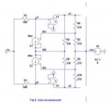
Now to calculate the gain of the feedback loop. Fig 8. is the simplified output stage (with the phases of G1 and G2 put right!) with the FETs removed (optional). The input is grounded and a voltage signal V1 is applied to the output. The ratio of v(n1) to V(out) or v(n2) to v(out) shows the gain of the loop.
I'll do the algebra in case anyone is interested.
The maths is tedious unless you assume perfect symmetry of the top and bottom halves. So assume gm1=gm2 and therefore v(n1)=v(n2). Remember, this is an ac analysis so dc levels are ignored.
The bottom half can now be ignored and effectively removed from the circuit.
Let i be the current through G1 and gm be the transconductance of G1.
v(fb0) = i.R4 + v(n1)
v(n1) = -i.R1
i = gm.[ v(fb1) - v(fb0) ] = gm.[ (v(n1) + v(out))/2 - i.R4 - v(n1) ]
substitute -v(n1)/R1 for i
-v(n1)/R1 = gm.v(n1)/2 + gm.v(out)/2 + gm.v(n1).R4/R1 - gm.v(n1)
which simplifies to
-v(out)/v(n1) = { 2.( 1 + gm.R4 )/(gm.R1) - 1 }
v(n1)/v(out) = - { (gm.R1) / [ 2 + gm.(2.R4 - R1) ] }
If you put in the values shown in the diagram, gm = 0.04, R1 = 680, R4 = 330, the ratio v(n1)/v(out) = -23.
The loop gain or "correction power" is 27dB. The real circuit will be different because the circuit values are different and there are some extra parts. Perhaps Andy or jcx would measure this in the full circuit simulation.
Happy Thanksgiving to those who celebrate it!
Now to calculate the gain of the feedback loop. Fig 8. is the simplified output stage (with the phases of G1 and G2 put right!) with the FETs removed (optional). The input is grounded and a voltage signal V1 is applied to the output. The ratio of v(n1) to V(out) or v(n2) to v(out) shows the gain of the loop.
I'll do the algebra in case anyone is interested.
The maths is tedious unless you assume perfect symmetry of the top and bottom halves. So assume gm1=gm2 and therefore v(n1)=v(n2). Remember, this is an ac analysis so dc levels are ignored.
The bottom half can now be ignored and effectively removed from the circuit.
Let i be the current through G1 and gm be the transconductance of G1.
v(fb0) = i.R4 + v(n1)
v(n1) = -i.R1
i = gm.[ v(fb1) - v(fb0) ] = gm.[ (v(n1) + v(out))/2 - i.R4 - v(n1) ]
substitute -v(n1)/R1 for i
-v(n1)/R1 = gm.v(n1)/2 + gm.v(out)/2 + gm.v(n1).R4/R1 - gm.v(n1)
which simplifies to
-v(out)/v(n1) = { 2.( 1 + gm.R4 )/(gm.R1) - 1 }
v(n1)/v(out) = - { (gm.R1) / [ 2 + gm.(2.R4 - R1) ] }
If you put in the values shown in the diagram, gm = 0.04, R1 = 680, R4 = 330, the ratio v(n1)/v(out) = -23.
The loop gain or "correction power" is 27dB. The real circuit will be different because the circuit values are different and there are some extra parts. Perhaps Andy or jcx would measure this in the full circuit simulation.
Attachments
Bob wrote:
I have a general comment about feedback methods to reduce distortion. In an algebraic equation you can simply remove distortion by forcing an equivalence, and your mathmatical force is unlimited. But in a electronic circuit your force must come from excess loop gain. The loop gain forces the input to the distorting device to become the value necessary to achieve a stable equilibrium in the loop. If you are lucky this equilibrium also minimizes the distortion at the output. All you have in your circuit is gain and a distorting device. Neither of these elements has the intelligence to calculate the inverse transfer function of the device so as to pre-distort the signal and then to "cancel" the distortion.
The term "error cancellation" when applied to Hawksford is a misnomer IMO. Cancellation is something you do after the event. Feed-forward is cancellation. Pre-distortion is where you use a pre-meditated block ahead of the device which has the inverse (distortion) transfer function of the device. Some might call "pre-distortion" circuit good old fashioned "linearization". John Curl is an expert at this through clever device matching.
IMO pre-distortion is the ideal if you can make an inverse function block - usually quite tricky, sometimes impossible. Feed-forward is next best, if you have a linear summer (which you don't in a power amp otherwise you wouldn't need to correct anything in the first place). Feedback can be powerful but it has some serious limitations: to fully correct you need infinite gain, which is impractical in a real circuit.
Any linear "correction" circuit that relies only on measuring the distortion of the device is a NFB system and necessarily requires infinite FB for complete correction. All these patents and eureka! papers are based on mathmatical slight of hand or oversight (perhaps unwittingly by the inventor) and are un-implementable. I include Hawksford's system (when a=1 and b=0) in this.
I had a look at the patent and fell into a sudden comma around about line 50 on page 3. So I don't a specific opinion on this patent.Maybe brian has an opinion on this circuit.
I have a general comment about feedback methods to reduce distortion. In an algebraic equation you can simply remove distortion by forcing an equivalence, and your mathmatical force is unlimited. But in a electronic circuit your force must come from excess loop gain. The loop gain forces the input to the distorting device to become the value necessary to achieve a stable equilibrium in the loop. If you are lucky this equilibrium also minimizes the distortion at the output. All you have in your circuit is gain and a distorting device. Neither of these elements has the intelligence to calculate the inverse transfer function of the device so as to pre-distort the signal and then to "cancel" the distortion.
The term "error cancellation" when applied to Hawksford is a misnomer IMO. Cancellation is something you do after the event. Feed-forward is cancellation. Pre-distortion is where you use a pre-meditated block ahead of the device which has the inverse (distortion) transfer function of the device. Some might call "pre-distortion" circuit good old fashioned "linearization". John Curl is an expert at this through clever device matching.
IMO pre-distortion is the ideal if you can make an inverse function block - usually quite tricky, sometimes impossible. Feed-forward is next best, if you have a linear summer (which you don't in a power amp otherwise you wouldn't need to correct anything in the first place). Feedback can be powerful but it has some serious limitations: to fully correct you need infinite gain, which is impractical in a real circuit.
Any linear "correction" circuit that relies only on measuring the distortion of the device is a NFB system and necessarily requires infinite FB for complete correction. All these patents and eureka! papers are based on mathmatical slight of hand or oversight (perhaps unwittingly by the inventor) and are un-implementable. I include Hawksford's system (when a=1 and b=0) in this.
traderbam said:[snip]In an algebraic equation you can simply remove distortion by forcing an equivalence, and your mathmatical force is unlimited. But in a electronic circuit your force must come from excess loop gain. [snip]
Brian,
I don't agree to this. You cannot 'force' anything in mathematics. Mathematical operations have a distinct correspondance to the real world. I have never seen a mathematical expression that predicted something and then in the real world it worked differently. If I had, I would have overthrown a vast body of physics and mathematics developed over ages.
Sometimes in mathematical models or equations we disregard some elements or details to focus on the main issue, and then later find that those details in reality prevent us to realise that what we developed in the model. I would venture that that is the case in ALL circuit calculations; they only differ to how much details you include and which you leave out. But the calculations of the details you include correspont to the real world. 100%.
I also have seen no proof that in electronics distortion reduction through feedback MUST come from excess loop gain. We tried a couple of examples and some maintain that they relay on excess loop gain. First of all, that is not agreed by all, secondly it is no proof that it always must be like that. I like to continue to think and play and test things to see how I can do better, don't take that away from me😉
Jan Didden
traderbam said:... you need infinite gain, which is impractical in a real circuit.
I love those british understatements. 🙂
traderbam said:.....
Any linear "correction" circuit that relies only on measuring the distortion of the device is a NFB system and necessarily requires infinite FB for complete correction. ....
Brian:
I find mildly amusing your distaste for the term "error correction".
The algebraic treatement emphasizing the error correction concept is no more unreal than the Fourier transform conversion from the time domain to the frequency domain. Sound in the end is no more than a time varying pressure field, frequency has no physical existence.
Of course it can allways be shown an ideal error correction scheme is equivalent to an infinite open loop gain if one manipulates the mathematical description so as to model it as a negative feedback system. This is strightforward, and barring real infinite gain blocks, some form of positive feedback must be involved. Again this is only a perspective which may satisfy some individuals.
Alternatively, looking at the same scheme form a different perspective - error correction - but taking into consideration constraints imposed by real world implementation, one can gather insights which are not readily apparent if one narrows the viewpoint for example only as a negative feedback topology.
Rodolfo
Christer. 😛
Rodolfo
I realise that everthing I am saying is undermining your work and I apologize for causing you animosity. At the same time I feel I ought to call it as I see it and I assume this debate is of some interest to other members.
I think we are sort of agreeing in a way. I am saying that the Hawksford system with a=1, b=0 (or any other a) is not just similar to a NFB system it is equivalent. They are one and the same. The diagrams "look" different but they are the same mathmatically.
The question I am posing is whether the topology of the Hawford "mathmatical" diagram is the best topology for a real circuit.
So far, no one has convinced me of why the Hawsford topology should make for a better NFB system than the conventional topology. Earlier, I gave reasons why I think it is probably worse. I could be wrong.
I am engaging in a detailed analysis of Bob's output stage so that the benefits and drawbacks may be revealled objectively.
Brian
PS: I don't really mind "error correction". I feel like PB2 does. But I do object to "error cancellation" when applied to a feedback system. I suppose error correction applies to all NFB circuits so my own amps can now be endowed with this trendy-sounding feature.
Rodolfo
I realise that everthing I am saying is undermining your work and I apologize for causing you animosity.
At the same time I feel I ought to call it as I see it and I assume this debate is of some interest to other members.I think we are sort of agreeing in a way. I am saying that the Hawksford system with a=1, b=0 (or any other a) is not just similar to a NFB system it is equivalent. They are one and the same. The diagrams "look" different but they are the same mathmatically.
The question I am posing is whether the topology of the Hawford "mathmatical" diagram is the best topology for a real circuit.
So far, no one has convinced me of why the Hawsford topology should make for a better NFB system than the conventional topology. Earlier, I gave reasons why I think it is probably worse. I could be wrong.
I am engaging in a detailed analysis of Bob's output stage so that the benefits and drawbacks may be revealled objectively.
Brian
PS: I don't really mind "error correction". I feel like PB2 does. But I do object to "error cancellation" when applied to a feedback system. I suppose error correction applies to all NFB circuits so my own amps can now be endowed with this trendy-sounding feature.
traderbam said:....
I realise that everthing I am saying is undermining your work and I apologize for causing you animosity. .....
No animosity at all !!! Only as said, mild amusement.
Please keep working, I discount you will readily acknowledge when time comes, that those of us supporting the error correction concept (not cancellation, leave that to marketing) backed by solid working evidence, were right.
Rodolfo
- Home
- Amplifiers
- Solid State
- Bob Cordell Interview: Error Correction