I'm a little busy today...so if anyone else wants to pitch in an answer then please go ahead...🙂Next installment...how much "correction" power does Bob's circuit provide?
lumanauw said:Hi, Bob Cordell,
If the output stage is bipolar, low biased classAB. Will putting Hawksford EC give huge improvement as if it was implemented in Mosfet output stage?
I have not applied EC to a bipolar output stage, but I believe that if it is applied properly it will give a very substantial improvement.
I would do it to a bipolar output stage that was biased on the high side, and perhaps one where the emitter ballast resistors were a little bit larger than the normal 0.27 or 0.33 ohms; I might go to 0.47 ohms. This will slightly increase static crossover distortion due to gm doubling in the over-biased case, but the EC will nicely kill the static crossover distortion. The advantage of the larger emitter ballast resistors is better thermal stability of the bipolar output stage at the higher Class AAB bias current.
Bob
janneman said:
Interesting question David. I have a related question: Bob, your design integrates H.ec as well as strong global feedback. If you would disconnect the H.ec, how much would the performance change? I understand that H.ec comes almost free the way you inplemented it, but it would be of interest to know.
Jan Didden
Good question, Jan. It is answered in my JAES paper on my site at www.cordellaudio.com in, I believe, Figure 15. That figure shows scope photos of the 20 kHz THD distortion at full power into 8 ohms with and without EC connected. Without EC, THD-20 is 0.02%. With EC, THD-20 is 0.0006%, better by a factor of 33 (30 dB).
Bob
Hi, Bob,
Thanks for the info 😀
This question is not about EC, but about output stage that uses many (maybe 10 or more) transistor pairs.
What is the advantage/drawback of using this much output transistors? Can this be near as good as using EC?
Thanks for the info 😀
This question is not about EC, but about output stage that uses many (maybe 10 or more) transistor pairs.
What is the advantage/drawback of using this much output transistors? Can this be near as good as using EC?
lumanauw said:Hi, Janneman,
May I add another one? 😀 How about a non-global feedback power amp, but have Hawksford EC in output stage (Like Steven's).
How does this compare to global feedback power amp+Hawksford EC (like Bob Cordell's)?
This is Steven's design :
http://www.diyaudio.com/forums/showthread.php?postid=330446#post330446
For those who prefer no global negative feedback, but who are OK with agressive local feedback, an amplifier using Hawksford EC without global feedback would make sense, at least in some sort of way. As I speculated in an earlier post, a cynical manufacturer could build such an amplifier with very good performance and advertize it as a no-feedback design, glossing over the local feedback that the EC actually represents. He could even advertize it as no-feedback with error correction, privately assering that EC is not negative feedback.
Bob
mikeks said:Folks, i think Hawksford (and Cordell) were preceded by Mr Henri Pichal as far back (at least!) as 1972!
Mike, I think not, but I could be wrong. Look at the circuit closely. Where is the positive feedback? There is none, as far as I can see. I'm not even sure this scheme works as advertized.
Maybe brian has an opinion on this circuit.
Bob

mikeks said:
Hi JCX
I run your netlist, but obtained a ''multiple instances of flag'' error.
...am i doing something wrong?
I think it means there are the same part names already in your LtSpice part lib as in the .include files
probably best to rename one or the other to be sure which model is being used
R46,47 not correctly renumbered in my .asc
lumanauw said:Hi, Bob,
Thanks for the info 😀
This question is not about EC, but about output stage that uses many (maybe 10 or more) transistor pairs.
What is the advantage/drawback of using this much output transistors? Can this be near as good as using EC?
Adding more pairs of output transistors allows you to safely operate at higher idle bias and reduce net output stage output impedance, thus reducing static crossover distortion, but this is certainly much more expensive in so many ways than using EC. Also, the added capacitance of all those transistors to drive could be painful.
Bob
lumanauw said:Hi, Bob,
I'm not clear about Xover distortion.
In an amp that uses collector (=drain) output, ie; common emitor (=source), is this kind of amp do not suffering Xover distortion?
It will also have crossover distortion. Any time the gain of the output stage changes as you go through crossover, you will have a static crossover distortion mechanism.
Bob
lumanauw said:Hi, Bob,
I'm not clear about Xover distortion.
In an amp that uses collector (=drain) output, ie; common emitor (=source), is this kind of amp do not suffering Xover distortion?
David,
What causes xover distortion? If at some point on the waveform only one output side delivers the bulk of the output signal, there MUST be a point where the load shifts from one side to the other -> xover. If that shift is not linear (and it is extremely hard if not impossible to make it perfectly linear) you have xover distortion.
You can answer your own question!
Jan Didden
Bob Cordell said:Mike, I think not, but I could be wrong. Look at the circuit closely. Where is the positive feedback? There is none, as far as I can see. I'm not even sure this scheme works as advertized.
Maybe brian has an opinion on this circuit.
Bob
Hi Bob,
I am not sure, but are you suggesting the presence of a positive feedback loop in your design?

Actually, i was referring to the claims made in his abstract.
janneman said:In my experience, a global nfb amplifier will measure better than non-global nfb amp with H.ec.
Jan Didden
This has been shown to be the case. See also:
M. G. Scroggie, “Distortion in negative feedback amplifiers,”
Wireless Engineer, vol. 15, p. 91, Feb. 1938.
Bob Cordell said:
Mike, I think not, but I could be wrong. Look at the circuit closely. Where is the positive feedback? There is none, as far as I can see. I'm not even sure this scheme works as advertized.
As far as I can see there is positive feedback in the same way as for Hawksford. Since the amp to be corrected is inverting in this case the resistive summing node actually performs a subtraction to get the error, which is then inverted and fed to the postivie input, which once again means a subtraction, since the source is fed to the inverting input. Maybe I overlook something, but it seems to me to be identical, on the block level, to the model of Hawksfords ec used earlier in the thread.
mikeks said:Hi folks.
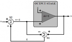
I am trying and failing to see any positive feedback here:
I think it was Traderbam who posted an equivalent diagram, where the feedback loop was replaced by two separate loops, one positive and one negative, by not subtracting the signals at S1 before feeding them back. That is equivalent, of course, on the block level of abstraction.
I think it may be deceptive to talk about the positive feedback loop in isolation, though, since it only exists simultaneously with another negative feedback loop, and they work together to define the system. Of course, block-level equivalences are not necessarily preserved when taking into account all further details in a real implementation, and I am not so sure it is wise to wiev the system as two separate loops in this way, instead of one loop as in mikeks diagram.
janneman said:Mike,
S1 bootstraps its own (left-hand side) input; that's pos feedback, no?
Jan
S1 is a differential amplifier. It could be a single transistor, making it an unbalanced diff. amp., as in Hawksford, or it could be a full blown emitter-coupled pair, as in Yokoyama.
No positive-feedback-by-design involved.
mikeks said:
Hi Bob,
I am not sure, but are you suggesting the presence of a positive feedback loop in your design?
Actually, i was referring to the claims made in his abstract.
Yes, if look at it correctly, you can always find a positive feedback loop in the Hawksford EC scheme. Brian has been correctly pointing this out.
Bob
- Home
- Amplifiers
- Solid State
- Bob Cordell Interview: Error Correction