mikeks said:
The difficulty is that positive feedback in a system increases distortion even as it increases the gain required to reduce it: .....
Reducing EC to a form of positive feedback leads (righlty) to this kind of conclusion.
Rodolfo
Hi Bob,
oh dear me, it's difficult to keep up the pace with this thread.
Anyhow I walked back and read the posts again, and I do agree with what you have said.
Especially your comments about the 2 types of crossover anomalies was good and I'm glad to see others have thought about it as I had, though I feel that especially BJT's could gain something from sliding bias (never turn off scheme) as their ft is so dependent on Ic, thats one big issue why I wouldn't like to turn off a BJT especially, if we look at a 30 MHz output BJT device at 100 mA (if shown in datasheet), their ft is rather 3 MHz than 30 MHz, FET's on the other hand don't get slow at low Id....
I can not myself speak to much for or against the sliding biasing (and MH's EC) as I have no practical experience with them so I am speculative here just using my intuation and knowledge of analog electronics, though some sliding bias designs I have viewed seem to work in a way that give the circuit an abrupt change never the less.
I don't see any problem with some slight transconductance changes as long as it's maintained softly. An abrupt change means always higher distortion frequency components giving the global FB node more job to solve it, so that lead me to think it's a matter of how we implement it.
I hope myself within a near future have a sliding bias based design of my own ready, but till then I have to be humble.
Cheers Michael
Bob Cordell said:
What you describe is essentially the same as so-called sliding bias, and I just recently touched on it in my post #623, second paragraph. Many people have tried variations of this scheme, but I have always found Hawksford error correction to be far more effective.Bob
oh dear me, it's difficult to keep up the pace with this thread.
Anyhow I walked back and read the posts again, and I do agree with what you have said.
Especially your comments about the 2 types of crossover anomalies was good and I'm glad to see others have thought about it as I had, though I feel that especially BJT's could gain something from sliding bias (never turn off scheme) as their ft is so dependent on Ic, thats one big issue why I wouldn't like to turn off a BJT especially, if we look at a 30 MHz output BJT device at 100 mA (if shown in datasheet), their ft is rather 3 MHz than 30 MHz, FET's on the other hand don't get slow at low Id....
Bob Cordell said:
This biggest problem as I see it is that just keeping the other transistor on, rather than letting it turn off, does not keep it contributing to the total transconductance of the output stage, and the variation of that total transconductance is what leads to static crossover distortion.
Others here on the board may have more positive experiences with these schemes to report, however.
Bob
I can not myself speak to much for or against the sliding biasing (and MH's EC) as I have no practical experience with them so I am speculative here just using my intuation and knowledge of analog electronics, though some sliding bias designs I have viewed seem to work in a way that give the circuit an abrupt change never the less.
I don't see any problem with some slight transconductance changes as long as it's maintained softly. An abrupt change means always higher distortion frequency components giving the global FB node more job to solve it, so that lead me to think it's a matter of how we implement it.
I hope myself within a near future have a sliding bias based design of my own ready, but till then I have to be humble.
Cheers Michael
Bob wrote:
How about we start by trying to understand what your output stage actual does?
It would be helpful if we had a spice model of it to do some measurements. Any volunteers out there?
Great. Thanks.Sure, I'll probably learn as much as anybody else in the process!
How about we start by trying to understand what your output stage actual does?
It would be helpful if we had a spice model of it to do some measurements. Any volunteers out there?
traderbam said:It would be helpful if we had a spice model of it to do some measurements. Any volunteers out there?
I think I could dig up my sim from a few years back. I used to modify my LTSpice standard.bjt, standard.mos etc. But this is bad for sharing projects. I've since seen the light about using "stock" standard.* files. But this old sim depended on some modified standard.* files with models added. I'll need to fix it up to use .include statements, set the supply voltages back to what they were in Bob's original design, and re-bias. This will take a little while. But I will post it sometime today.
mikeks said:
It is exceeding unlikely that a single transistor can be made to generate more gain with positive feedback
He called it "active device"... If it can't, the system with them and passive devices can.
Ultima Thule said:I can not myself speak to much for or against the sliding biasing (and MH's EC) as I have no practical experience with them so I am speculative here just using my intuation and knowledge of analog electronics, though some sliding bias designs I have viewed seem to work in a way that give the circuit an abrupt change never the less.
I don't see any problem with some slight transconductance changes as long as it's maintained softly. An abrupt change means always higher distortion frequency components giving the global FB node more job to solve it, so that lead me to think it's a matter of how we implement it.
In my experience all these active bias techniques work much
better if there is a large quiescent bias to begin with, greatly
smoothing the transfer curve. As an example, in 1975 the 800A
idled at about 200 watts/ch.
Nelson Pass said:
In my experience all these active bias techniques work much
better if there is a large quiescent bias to begin with, greatly
smoothing the transfer curve. As an example, in 1975 the 800A
idled at about 200 watts/ch.
My today's 300W idles at 620W per channel. Anyway, an amp with tubes in output will consume more for such sonical quality.
Bob Cordell said:
........
This biggest problem as I see it is that just keeping the other transistor on, rather than letting it turn off, does not keep it contributing to the total transconductance of the output stage, and the variation of that total transconductance is what leads to static crossover distortion.
........
Mr. Cordell:
Interestingly, global error correction schemes seem less vulnerable with respect to loss of transconductance at crossover, since they are not dependent on open loop gain (including output stage), but on the summing node performance.
Janemann's insight comes to mind here, when he (re) christened EC as "feedback on demand".
Of course I endorse your tennet that "devil is in the details" anyway, when confronted with an actual implementation.
Rodolfo
Okay, here is a sim of Bob's output stage. There are some differences in component values. If you want to make changes, do so, then do a DC operating point, adjusting R16 to get 150 mA bias current in the output stage. No device types were specified in Bob's article, so I've been a bit "fast and loose" with these. The output device models are ones I've created that are LTSpice-specific VDMOS models. These take into account varying Cds and Cgd with their corresponding voltages. These models are described in this post. The FQA12P20 is a Fairchild IRFP9240 substitute.
There is a THD sim set up using a .FOUR statement. To view the THD, do a transient analysis, then View, SPICE error log.
There is a THD sim set up using a .FOUR statement. To view the THD, do a transient analysis, then View, SPICE error log.
Attachments
Mike,
I have not tried that one. I think I'll leave it to whoever would like to volunteer to do it 🙂.
I have not tried that one. I think I'll leave it to whoever would like to volunteer to do it 🙂.
Nelson Pass said:
In my experience all these active bias techniques work much
better if there is a large quiescent bias to begin with, greatly
smoothing the transfer curve. As an example, in 1975 the 800A
idled at about 200 watts/ch.
Very good point, Nelson. Did you ever worry about "gm doubling", as described by Self?
In your view, what was the main contribution to performance made by your sliding bias scheme? For example, was it more in the nature of smoothing the gm transition curve with respect to static crossover distortion, or was it some dynamic high-speed benefit that arose from not fully turning off the output transistors, or was it something else altogether?
Thanks,
Bob
andy_c said:Okay, here is a sim of Bob's output stage. There are some differences in component values. If you want to make changes, do so, then do a DC operating point, adjusting R16 to get 150 mA bias current in the output stage. No device types were specified in Bob's article, so I've been a bit "fast and loose" with these. The output device models are ones I've created that are LTSpice-specific VDMOS models. These take into account varying Cds and Cgd with their corresponding voltages. These models are described in this post. The FQA12P20 is a Fairchild IRFP9240 substitute.
There is a THD sim set up using a .FOUR statement. To view the THD, do a transient analysis, then View, SPICE error log.
Nice work, Andy.
I have a confession to make. Even though I had been using SPICE (and its predecessor SLIC) at Bell Labs for years during the Seventies as a linear IC designer, I did not SPICE the MOSFET Power Amplifier with Error Correction.
Cheers,
Bob
Bob Cordell said:
Yes, the same neat thing happens with my Hawksford circuit when I use the pot. It is a great demonstration of the operation of the EC.
Bob
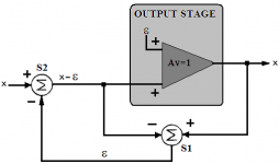
From the figure below it becomes clear that exact error cancellation is accomplished in principal by merely introducing error at the power stage's input (summed, of course, with the desired stimulus X) of the same magnitude but of opposite phase to that generated by the output stage.
Attachments
Bob Cordell said:I have a confession to make. Even though I had been using SPICE (and its predecessor SLIC) at Bell Labs for years during the Seventies as a linear IC designer, I did not SPICE the MOSFET Power Amplifier with Error Correction.
Thanks Bob. Lots of things have changed for the better as far as usability of SPICE and availability of models are concerned. Writing computer programs back then was a complete PITA. Heck, my original FORTRAN class used punch cards. That was awful. It's amazing how far computer-aided design techniques have come since then.
andy_c said:
Thanks Bob. Lots of things have changed for the better as far as usability of SPICE and availability of models are concerned. Writing computer programs back then was a complete PITA. Heck, my original FORTRAN class used punch cards. That was awful. It's amazing how far computer-aided design techniques have come since then.
Do they include models of human perceptions and imaginations?

Wavebourn said:Do they include models of human perceptions and imaginations?
I think you know the answer to that one 🙂.
andy_c said:
.... Heck, my original FORTRAN class used punch cards. ....
My first computer program was a deck of 80 punched cards in Fortran too, find all solutions for the 8 chess queens problem. It was 1970 and run on an IBM360, took 1' 1" and worked the first try.
This last, never happened again to this day...
Rodolfo
ingrast said:
My first computer program was a deck of 80 punched cards in Fortran too, find all solutions for the 8 chess queens problem. It was 1970 and run on an IBM360, took 1' 1" and worked the first try.
This last, never happened again to this day...
Rodolfo
I hated programming being a student... Fortran, perforated cards, long list with error messages, and trying to understand what did I program couple of weeks ago and what that all error messages are about...
I would probably commit suicide if anybody told me that 30 years after I will manage 150 boxes with many types of Unixes. 😎
ingrast said:My first computer program was a deck of 80 punched cards in Fortran too, find all solutions for the 8 chess queens problem. It was 1970 and run on an IBM360, took 1' 1" and worked the first try.
Wow, think of the probability of that. That's like 1 divided by the number of atoms in the universe or something 🙂.
This last, never happened again to this day...
ROFL!
I believe we used the IBM 360 also. The computer center was really crowded, so even if I waited until midnight, I'd still have to wait in line for punch card machines. Then I'd punch the cards and give them to some guy in a room that was like a big closet. Then the next morning I'd find out my program didn't compile. After that, I swore I'd never touch a computer again. And I didn't for 10 years until I built a 286 clone.
- Home
- Amplifiers
- Solid State
- Bob Cordell Interview: Error Correction