traderbam said:[snip]Since the forward gain for this system is created by positive feedback, any error at the output will be bigger than it would have been if the forward gain had been generated cleanly.
I suspect this will also show up as a higher output Z than a conventional NFB system, when both have identical forward gain.
Brian
Brian,
If the ec makes the Vout depent only on Vin, whatever the gain block, that implies zero Zout. By definition, Zout does not depend in any way from the load.
Jan Didden
janneman said:
Rodolfo,
I'm not 100% sure about which topology you talk, but perfect null IS possible with an adjustment. In fact, in my circuit, you can go "throug the null', kind of overcompensate, and the distortion re-appears again but with flipped phase.
Jan Didden
Jan:
It is not really a "null" but a minimum. This is due to the fact the summing node cannot fail to include an active path, thus making for a complex (phase shifting) transfer. So we are substracting 2 non colinear vectors and cannot avoid a non zero result.
Rodolfo
ingrast said:
Jan:
It is not really a "null" but a minimum. This is due to the fact the summing node cannot fail to include an active path, thus making for a complex (phase shifting) transfer. So we are substracting 2 non colinear vectors and cannot avoid a non zero result.
Rodolfo
Agreed, a minimum, not a null.
Jan wrote:
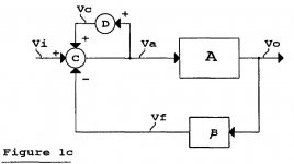
Yep. Consider your fig 1c.
The forward path gain is: Gf = A/(1-D)
The closed loop gain is: Vo/Vi = A/(1 - D + B.A)
The sensitivity of CL gain to changes in A is: S = (1 - D)/[(1 - D + B.A)^2]
You see that the sensitivity to changes in A is a minimum when D = 1. It is positive when D<1 and negative when D>1. This is your "nulling" effect.
But the system has no advantage over a fixed forward gain system. All this does is make you have to adjust for maximum forward gain. Why not just build it with maximum forward gain?
Brian
In fact, in my circuit, you can go "throug the null', kind of overcompensate, and the distortion re-appears again but with flipped phase.
Yep. Consider your fig 1c.
The forward path gain is: Gf = A/(1-D)
The closed loop gain is: Vo/Vi = A/(1 - D + B.A)
The sensitivity of CL gain to changes in A is: S = (1 - D)/[(1 - D + B.A)^2]
You see that the sensitivity to changes in A is a minimum when D = 1. It is positive when D<1 and negative when D>1. This is your "nulling" effect.
But the system has no advantage over a fixed forward gain system. All this does is make you have to adjust for maximum forward gain. Why not just build it with maximum forward gain?
Brian
Attachments
Rodolfo wrote:
So you are saying the concept of EC cannot work in the real world because infinite gain is impossible. Then you say this is ok because otherwise the concept would be of little use. 🙄 😀
Defining "EC" as NFB with infinite gain is not just an alternative viewpoint it is a mathmatical equivalence. The fig 1c circuit IS a NFB loop with infinite loop gain when D = 1. In your real circuit you cannot achieve infinite forward gain without total instability, so you are forced to build a NFB loop with a limited and rolled-off forward gain when D=1. By adjusting D you vary both the loop gain of the NFB loop and its gain margin.
Brian
If you do the math, you will find an infinite OL gain because cancellation implies a division by 0, which is an alternative viewpoint. Of course this does not hold in the real world, in fact it is not even possible, which is just fine, for otherwise the concept should be of little use.
So you are saying the concept of EC cannot work in the real world because infinite gain is impossible. Then you say this is ok because otherwise the concept would be of little use. 🙄 😀
Defining "EC" as NFB with infinite gain is not just an alternative viewpoint it is a mathmatical equivalence. The fig 1c circuit IS a NFB loop with infinite loop gain when D = 1. In your real circuit you cannot achieve infinite forward gain without total instability, so you are forced to build a NFB loop with a limited and rolled-off forward gain when D=1. By adjusting D you vary both the loop gain of the NFB loop and its gain margin.
Brian
traderbam said:Rodolfo wrote:
So you are saying the concept of EC cannot work in the real world because infinite gain is impossible. Then you say this is ok because otherwise the concept would be of little use. 🙄 😀
The division by zero requirement of "EC" is not an alternative viewpoint it is a mathmatical equivalence. The fig 1c circuit IS a NFB loop with infinite loop gain when D = 1. In your real circuit you cannot achieve infinite forward gain without total instability, so you are forced to build a NFB loop with a limited and rolled-off forward gain when D=1. By adjusting D you vary both the loop gain of the NFB loop and its gain margin.
Brian
??? Division by zero is (mathematically) illegal, so for me that translates to mean that whatever we calculate is valid provided the forward gain A (by which we divide) is NOT zero!
Jan Didden
Bob Cordell said:
I also know that three or four different models of his [Halcro] amplifiers have been reviewed in Stereophile, and not one of them has yet come close to its claimed distortion spec.
Bob
True.

Indeed, the DM58 achieves roughly the same linearity across the audio band as your JAES design.
Jan,
Is there any difference between your fig 1c and a NFB loop with a forward gain of A/(1-D)?
Is there?
(I've made c=1 for simplicity - this doesn't effect the result)
Is there any difference between your fig 1c and a NFB loop with a forward gain of A/(1-D)?
Is there?
(I've made c=1 for simplicity - this doesn't effect the result)
mikeks said:
True.
Indeed, the DM58 achieves roughly the same linearity across the audio band as your JAES design.
... and what is also apparent in the Stereophile THD plot is that the AP built-in 22kHz lp filter is engaged. Therefore, harmonics of test signals above 10kHz are attenuated and the plot does not give a true picture (as in: looks better than it is) above 10kHz.
Jan Didden
Stereophile wrote:
Mike, objective comparison degenerates into conjecture when the measurement system limitations dominate the measurement result. Not to mention the THD methods loose correlation to sound quality.
I think this is more important:
Does anyone have a sound comparison with Bob's amplifier?
Fig.3 shows the THD+noise percentage plotted against frequency at 157W into 8 ohms. It is 0.0006% or less across most of the band, rising very slightly above 10kHz. I can't swear to the accuracy of this figure, however; even at this high power, the Halcro's intrinsic distortion level appears to be of the same order as the output of the Audio Precision System One signal generator!
Mike, objective comparison degenerates into conjecture when the measurement system limitations dominate the measurement result. Not to mention the THD methods loose correlation to sound quality.
I think this is more important:
The Halcro dm58 is a paradigm-destroying component that could well justify the creation of a "Class A+" amplifier category in "Recommended Components." It is really that good. I don't entirely know or understand why that is so, and Bruce Candy is giving no secrets away, but the unassailable proof was in the hearing. Whatever its flaws may be, their discovery may have to wait until someone, somewhere, has developed an even better amplifier.
Does anyone have a sound comparison with Bob's amplifier?
janneman said:.....and what is also apparent in the Stereophile THD plot is that the AP built-in 22kHz lp filter is engaged. Therefore, harmonics of test signals above 10kHz are attenuated and the plot does not give a true picture (as in: looks better than it is) above 10kHz. Jan Didden
Indeed, i suspect THD+N at a more realistic measurement bandwidth of, say, 80KHz, significantly exceeds 10ppm beyond 15KHz.
janneman said:
Rodolfo,
I'm not 100% sure about which topology you talk, but perfect null IS possible with an adjustment. In fact, in my circuit, you can go "throug the null', kind of overcompensate, and the distortion re-appears again but with flipped phase.
Jan Didden
Yes, the same neat thing happens with my Hawksford circuit when I use the pot. It is a great demonstration of the operation of the EC.
Bob
traderbam said:Jan wrote:
But the system has no advantage over a fixed forward gain system. All this does is make you have to adjust for maximum forward gain. Why not just build it with maximum forward gain?
Brian
Brian,
The Devil is in the details of the implementation. If you try to do it topologically as in your diagram with a real piece of high gain, it will not work well, and may likely be unstable. Try it.
Bob
Hi Bob,
Before the argument degenerates into "suck it and see", will you agree with me, or offer an argument against, that your "EC" topology is, in theory, equivalent to an ordinary NFB loop?
I claim to have proven this mathmatically.
Brian
Before the argument degenerates into "suck it and see", will you agree with me, or offer an argument against, that your "EC" topology is, in theory, equivalent to an ordinary NFB loop?
I claim to have proven this mathmatically.
Brian
mikeks said:
True.
Indeed, the DM58 achieves roughly the same linearity across the audio band as your JAES design.
Yes, although it appears the Halcro just makes 0.001% at 20 kHz at 157 Watts (not full power), and mine does 0.0006% at 20 kHz at full power.
More importantly, however, it does not come close to its actual spec of less than 0.0001%. Of course, the AP System One is near its limit here, but based on my knowledge of the System One, I think the distortion in those plots is real, so obviously the Halcro appears to have missed its spec.
Note also, the twin-tone 19 khz & 20 kHz spectra. There are real lines there. If Halcro was meeting its agressive spec on this test as well, its IM lines would be in the grass.
This is a very good amplifier, and there would be no complaint if it spec'd a still very good 0.001% THD out to 20 kHz. However, they make a very big deal of their extraordinarily low claimed distortion, so they probably should be taken to task over the big miss, even though it is unlikely anyone will ever hear the difference between 0.001 and 0.0001%. Live by the sword, die by the sword.
Bob
Hi, Mikeks,
In the Stereophile's DM58 article that you pointed, in fig4 and fig5, the residuals, are they high order ones? Is this high order residuals are typical of EC amps?
In the Stereophile's DM58 article that you pointed, in fig4 and fig5, the residuals, are they high order ones? Is this high order residuals are typical of EC amps?
janneman said:
... and what is also apparent in the Stereophile THD plot is that the AP built-in 22kHz lp filter is engaged. Therefore, harmonics of test signals above 10kHz are attenuated and the plot does not give a true picture (as in: looks better than it is) above 10kHz.
Jan Didden
Actually, I believe that the AP LPF filter is at 80 kHz, but I could be wrong. In my tests of my amplifier I had the THD LPF at 200 kHz, so your point is still well-taken.
This is why I strongly prefer the CCIF spectral analysis test these days.
Bob
traderbam said:Stereophile wrote:
Mike, objective comparison degenerates into conjecture when the measurement system limitations dominate the measurement result. Not to mention the THD methods loose correlation to sound quality.
I think this is more important:
Does anyone have a sound comparison with Bob's amplifier?
Don't throw the baby out with the bath water. I'm not saying you can hear the difference between 0.001 and 0.0001, but if somebody stakes their corporate reputation on achieving the latter, they should be taken to task when they don't.
The AP System One typically has a residual of less than 0.001% at 20 kHz, so it looks like it is not dominating the result, but I agree this is getting close to conjecture. If you look at the CCIF IM plots, there is little room for conjecture when you compare those results to Halcro's published specifications. Also note, that those IM lines are real, since the Boulder actually has lower IM lines in its review.
Its pretty much the same as when the Chord amplifier missed its power output spec by nearly a factor of two. It still produces more power than than most people need, but a $90K amplifier should more than meet its spec. It's an integrity thing - something that this industry could use a bit more of.
Bob
traderbam said:Hi Bob,
Before the argument degenerates into "suck it and see", will you agree with me, or offer an argument against, that your "EC" topology is, in theory, equivalent to an ordinary NFB loop?
I claim to have proven this mathmatically.
Brian
Yes, I agree, and I've said that before. Just be careful with the word ordinary; some people might not see a NFB loop that encloses a PFB loop with theoretically infinite gain as ordinary. The physical/topological implementation is also not particularly ordinary, either; that is why I said the devil is in the details.
Your really need to get a hold of the Vanderkoy/Lipshitz AES preprint, circa 1984 or 1985, where they showed mathematically that the Hawksford EC could be viewed as a NFB.
What difference do the semantics make, anyway? Where are you going with this? It works, doesn't it? I'm not trying to argue with you, but would like to better understand what the burning issue is here.
Bob
Bob Cordell said:
Don't throw the baby out with the bath water. I'm not saying you can hear the difference between 0.001 and 0.0001, but if somebody stakes their corporate reputation on achieving the latter, they should be taken to task when they don't.
..... but a $90K amplifier should more than meet its spec. It's an integrity thing - something that this industry could use a bit more of.
Bob
Rodolfo
- Home
- Amplifiers
- Solid State
- Bob Cordell Interview: Error Correction