This is quite fascinating. I think we are talking about different gains.There is no 'hidden' feedback that uses excess loop gain to decrease the errors because there IS NO excess gain.
Perhaps you are referring to a complementary pairing where two EC amplifers are conjoined. Like in Bob's output stage. In this case the common mode excess gain is small, agreed. I'm talking about the differential mode excess gain.
Brian
I'm still not sure what that buys you, though....It's the resulting effective feedback that's important.
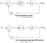
Ok, I'll risk veering on to the pavement with the next diagram. Fig. 4 is Fig 2 with the "null" factor "a" included and I have expressed the positive feedback loop gain as an equation. When "a" is set to 1, as Hawsford EC requires, you get fig 5. I claim the resulting effective feedback is infinite.
Attachments
Hi, Janneman,
In Bob Cordell's mosfet amp with EC, as I understand it, the EC action is actually limited (adding and substracting action) by the voltage drop of R34-R35 (680ohm). EC in this cct can be done only at the range of voltage drop at these R34-R35, EC system cannot do more or less than max drop at these resistors. Am I wrong here?
Hi, UpupaEpops,
Your website in English is still empty?
because there IS NO excess gain.
In Bob Cordell's mosfet amp with EC, as I understand it, the EC action is actually limited (adding and substracting action) by the voltage drop of R34-R35 (680ohm). EC in this cct can be done only at the range of voltage drop at these R34-R35, EC system cannot do more or less than max drop at these resistors. Am I wrong here?
Hi, UpupaEpops,
Your website in English is still empty?
traderbam said:
Ok, I'll risk veering on to the pavement with the next diagram. Fig. 4 is Fig 2 with the "null" factor "a" included and I have expressed the positive feedback loop gain as an equation. When "a" is set to 1, as Hawsford EC requires, you get fig 5. I claim the resulting effective feedback is infinite.
Hi Brian,
I agree that figs 4 & 5 are 'infinite feedback'. Fig 4 is in effect the circuit I described in the aes preprint. There is a lot of excess gain in these two circuits. In practical experiments, building an amp according to fig 4, all looks well until clipping. At that point the nfb becomes inoperative, but the pos fb inner loop is still active, so what you see is enormous gain making the output stick to one of the rails... Actually fried a couple of speakers that way.
But, when I agreed that your initial fig 1 and fig 2 are equivalent, that is in terms of results, black-box-wise so to say. I'm not sure whether they internally achieve that result by the same means, or that fig 2 (and therefore figs 4 & 5) are actually equivalent to Hawksford. I'm not trying to split hairs; this is pretty complex for me.
Jan Didden
Jan,
It makes sense that the circuit would go to the rail without output feedback.
The key thing I want to show is that the functional result is identical to a simple NFB loop. Hence, it is my opinion that implementing the Hawksford diagram node for node is unecessarily complex: it creates the need for 3 inputs rather than 2 and requires "tuning". I don't yet see any point in this.
Brian
Which is one of the reasons why i am beginning to think Yokoyama's implementation might be the optimal approach to Hawksford.
Yokoyama is a similar thing in a different arrangement. He claims that his circuit's output is only dependent on Vi and B and has no sensitivity to the output transistors. That is patently impossible  unless there is infinite feedback involved (eg: perfect pre-distortion) or perfect feed-forward.
unless there is infinite feedback involved (eg: perfect pre-distortion) or perfect feed-forward.You are missing one point:traderbam said:
The key thing I want to show is that the functional result is identical to a simple NFB loop. Hence, it is my opinion that implementing the Hawksford diagram node for node is unecessarily complex: it creates the need for 3 inputs rather than 2 and requires "tuning". I don't yet see any point in this.
Brian
Classic 'infinite' loop gain negative feedback works with infenitesimal difference signal, which in reality may mean not much higher than noise floor or any disturbace (e.g. RFI?) to differencial signal will matter.
In contrary feedback error correction works with higher level signals and relies on matching.
Adam
traderbam said:Jan,
It makes sense that the circuit would go to the rail without output feedback.
The key thing I want to show is that the functional result is identical to a simple NFB loop. Hence, it is my opinion that implementing the Hawksford diagram node for node is unecessarily complex: it creates the need for 3 inputs rather than 2 and requires "tuning". I don't yet see any point in this.
Brian
Hi Brian,
I think anyone would be hard-pressed to find a simpler circuit than Hawksford's that performs error correction as well. The tuning is a fascinating part of it that I see as a feature, rather than a drawback. You can always tune your prototype and then build the rest with one percent resistors. They'll be like peas in a pod in most cases. The Hawksford circuit is elegant, tight, and synergistic at the transistor level. Even if it can be viewed as working because of a very high amount of local NFB, it does so very well because the loop is very tight. As we agreed earlier, this is certainly no cause for complacency in regard to the need for frequency compensation, however.
You are not alone, however. In his later patent on "error correction" Bruce Candy of Halcro departed from the Hawksford circuit, citing the "need for tuning" as a disadvantage. Poor guy, he can't afford to have a tech turn a pot in five minutes in preparing a $20,000 monoblock for the customer?
His answer to the Hawksford circuit was gobs and gobs of high-order feedback loops, both local and global, and a far more complex circuit overall. I honestly do not know whether he ever used that approach in place of the Hawksford approach in any of his amplifiers. In the real world, there is often a big difference between what one says in a patent and what one does in the real world.
Bob
traderbam said:Yokoyama is a similar thing in a different arrangement. He claims that his circuit's output is only dependent on Vi and B and has no sensitivity to the output transistors. That is patently impossible
Actually, i didn't even bother to read the man's prose: i reckoned, in this case, that the schematics should do all the talking, and they did.

While Hawksford uses differentially driven single BJTs for error extraction, Yokoyama et al use a much simpler, heavily degenerated and, consequently, far more linear differential pair.
Further, with greatly reduced component count, the later drives the TIS's current source in phase opposition to the TIS, thereby effecting the required invasion of the extracted error signal ''e'' shown below.
This eliminates the low impedance drive required by the Hawksford scheme to properly and resistively define the collector loads in his error amplifiers.
Indeed, Yokoyama et al could be readily improved by, for instance, using independent voltage rails of greater modulus than those of the output stage; this would accommodate the compliance of an active current sink in place of the capacitively bootstrapped resistive tail for the error extractor.
Even so, this arrangement is significantly more supply rail-efficient than Hawksford's arrangement.
Attachments
Bob Cordell said:You can always tune your prototype and then build the rest with one percent resistors.
One source of error is that Hawksford's formula for the resistor values neglects the re of the error correction transistors, assuming their gain is just RC / RE. A few years ago I put your output stage into a sim. I derived a really ugly formula for the cross-coupled resistors that took the error correction transistor re into account. It was a while ago, but I think I got 10 dB less distortion in the sim with the revised values.
andy_c said:
One source of error is that Hawksford's formula for the resistor values neglects the re of the error correction transistors, assuming their gain is just RC / RE. A few years ago I put your output stage into a sim. I derived a really ugly formula for the cross-coupled resistors that took the error correction transistor re into account. It was a while ago, but I think I got 10 dB less distortion in the sim with the revised values.
Yes, andy, you are exactly right. That's why it is wise to have a trim for the prototype. But once trimmed, things stay put pretty well, and fixed precision resistors can be used if one is not after the last smidgeon of error correction. I personally always put the trimmer in.
Bob
Hi, Bob Cordell,
What do you think of patent #4,366,432? It is about ordinary PS (using transformer) that is pursued to act like batteries.
The author done this in an interesting way. He uses constant current+constant voltage to get the effect. He tries to make the draw from the transformer constant by making sacrificial 2nd loop of current draw, very close to the main cct.
The practical implementation of this is in STAX DA100 power amp schematic.
http://www.diyaudio.com/forums/showthread.php?s=&threadid=86377&highlight=
It is implementation of patent #4,366,432 and #4,406,990.
Jacco said it is good amp 😀
Does this mean that it is not possible or economical for us to make a power supply as good as a battery?
What do you think of patent #4,366,432? It is about ordinary PS (using transformer) that is pursued to act like batteries.
The author done this in an interesting way. He uses constant current+constant voltage to get the effect. He tries to make the draw from the transformer constant by making sacrificial 2nd loop of current draw, very close to the main cct.
The practical implementation of this is in STAX DA100 power amp schematic.
http://www.diyaudio.com/forums/showthread.php?s=&threadid=86377&highlight=
It is implementation of patent #4,366,432 and #4,406,990.
Jacco said it is good amp 😀
Greetings form Tokyo - great thread
Bob, hope you can shed some light on questions below
1. Are there any practical implementations of Hawksfords error correction (as used in your design) on a bipolar amp?
2. What is your view on sliding bias as an aproach to reducing bipolar output distortion and how would this compare as an approach to say the Hawksford error correction if the answer to 1 about is yes?
🙂
Unfortunately, the "X Factor" still seems to be very important in audio and human perception. We are not any closer to answers ... 😉
Darkfenriz wrote:
Can you show me this in the equations? You see, when I look at the Hawksford equations they reduce to a simple NFB system, with high gain. When Andy c and I measure the "difference signal" loop gain in his Spice circuit we get high gain: meaning a small difference signal will cause a large output change.You are missing one point: Classic 'infinite' loop gain negative feedback works with infenitesimal difference signal, which in reality may mean not much higher than noise floor or any disturbace (e.g. RFI?) to differencial signal will matter. In contrary feedback error correction works with higher level signals and relies on matching.
traderbam said:Darkfenriz wrote:
Can you show me this in the equations? You see, when I look at the Hawksford equations they reduce to a simple NFB system, with high gain. When Andy c and I measure the "difference signal" loop gain in his Spice circuit we get high gain: meaning a small difference signal will cause a large output change.
Brian:
I beg to differ. In Hawksford ec, you are seeing small differences (the difference between as-is and should-be Vout); the resulting (small) error results in small output changes (to bring the as-is to the should-be).
I am still wrestling with this: in H.ec the small error component gets a gain of approximately (to first order) 1, so where is the high difference gain?
Jan Didden
darkfenriz said:
You are missing one point:
Classic 'infinite' loop gain negative feedback works with infenitesimal difference signal, which in reality may mean not much higher than noise floor or any disturbace (e.g. RFI?) to differencial signal will matter.
In contrary feedback error correction works with higher level signals and relies on matching.
Adam
Adam,
In H.ec you also work with small signals: the difference between the actual Vout and the required Vout for zero distortion. In practise you also at a certain point hit the noise level as a limitation to how exact you can null the error.
Jan Didden
Hi, Bonsai,
The one that works very well is Nelson Pass' #3,995,228.
I tought of one here : http://www.diyaudio.com/forums/showthread.php?postid=611752#post611752
Another one here :
http://www.diyaudio.com/forums/showthread.php?postid=524217#post524217
It turns out that someone has patented it 25 years before I think of it, the drawing is exactly in the first page of the patent 😀 #4,160,216
I found that non-turnoff scheme is much less problematic than EC. They are not the same thing, but they shoot at the same point, ie; output stage. Much less problematic in implementation usually sounds better (not always, though).2. What is your view on sliding bias as an aproach to reducing bipolar output distortion and how would this compare as an approach to say the Hawksford error correction if the answer to 1 about is yes?
The one that works very well is Nelson Pass' #3,995,228.
I tought of one here : http://www.diyaudio.com/forums/showthread.php?postid=611752#post611752
Another one here :
http://www.diyaudio.com/forums/showthread.php?postid=524217#post524217
It turns out that someone has patented it 25 years before I think of it, the drawing is exactly in the first page of the patent 😀 #4,160,216
Bob Cordell wrote:
When this is done it will become clear why Candy has moved away from Hawksford.
Do I see a gauntlet on the floor?😉 Have confidence, we are going to achieve a simpler circuit that performs better. But this is relatively easy. The real learning is in understanding that Hawksford (a=1, b=0) is equivalent to a simple NFB loop. I sense some doubts so let's deal with this first.I think anyone would be hard-pressed to find a simpler circuit than Hawksford's that performs error correction as well.
When this is done it will become clear why Candy has moved away from Hawksford.
Fascinating? Elegant? Each to their own, I suppose.🙂 Let's keep this objective: what do you mean by "tight"?The tuning is a fascinating part of it that I see as a feature, rather than a drawback. You can always tune your prototype and then build the rest with one percent resistors. They'll be like peas in a pod in most cases. The Hawksford circuit is elegant, tight, and synergistic at the transistor level. Even if it can be viewed as working because of a very high amount of local NFB, it does so very well because the loop is very tight.
- Home
- Amplifiers
- Solid State
- Bob Cordell Interview: Error Correction