Re: Open the loop
Pete, (and Brian),
I have no time today or tomorrow to work on this, just trying to shoehorn in a few miniutes now and then, so please forgive me the erratic responses.
To the quoted post: In my protopype amp I have a two switches that enable or disable the EC by breaking the loop at B, both for the output stage EC loop as well as the Vas EC loop (this Vas has OL gain of 22 only). What I see is indeed that the gain stays substantially the same with only the distortion level changing dramatically. This is, as noted, completely different from a 'traditional' fb loop.
Jan Didden
PB2 said:Here I have opened the feedback loop by grounding the feedback input to the first summer. Note that the system gain does not change, it is unity with 10V in and 10V (plus distortion) out. The gain changes in traditional feedback systems when we open the loop. The circuit and waveforms are given below. It can be seen that the gain does not change, the output is now distorted obviously, and the feedback term V(va) is just the correction term with no signal. While some may claim that these can be mathematically transformed into traditional negative feedback systems, it is clear that real implementations are nothing like traditional negative feedback systems. Show me a traditional negative feedback system with a distortion null control.
http://baselaudiolabs.googlepages.com/hec_not_negfb3D.PNG
http://baselaudiolabs.googlepages.com/hec_not_negfb3.PNG
Pete, (and Brian),
I have no time today or tomorrow to work on this, just trying to shoehorn in a few miniutes now and then, so please forgive me the erratic responses.
To the quoted post: In my protopype amp I have a two switches that enable or disable the EC by breaking the loop at B, both for the output stage EC loop as well as the Vas EC loop (this Vas has OL gain of 22 only). What I see is indeed that the gain stays substantially the same with only the distortion level changing dramatically. This is, as noted, completely different from a 'traditional' fb loop.
Jan Didden
PB2 said:I do not read every post here, and I am a bit surprised if the discussion here now applies to the disagreement that started back around post 555 as it would seem that people were talking about different problems. OK ... well ... I'm not surprised.
Hi Pete,
Right from post 555, the subject is where to break the loop and, closely related to this "...that the difference between output and input is driven to zero by virtue of the enormous forward gain that is generated by a positive feedback loop" (Brian)
First off, this discussion is about the local feedback loop of the output stage alone, and therefore comments about loop stability as if it was the major loop make stability concerns
...............
Bob's real design works and is stable, yet some here are claiming such designs will not be stable.
To the best of knowledge, nobody has said that. But I'm convinced that EC has a negative influence on the stability margin. Why else would Bob say: "I think that one would have to be borderline suicidal to use this circuit without any output HF isolating inductor at all"
What traditional negative feedback design has a null control?
If the NFB loop gain approaches infinity, then the distortion drops to almost 'null'
Cheers, Edmond.
(sorry, had to edit this as I made a blunder)
Jan wrote:
I believe the contention is that you keep denying C as the correct place to measure the feedback. This is so self-evident to me that I cannot conceive of why you think otherwise.
Jan wrote:
Yes.With the switch in the lower position, we can break the loop at A, B or C, always measuring the same value for the loop gain. Obviously, when we put the switch in the upper position, the loop gain measurements at A and B will not change, but at C will, because we now measure a different 'loop' at C than before.
Yes, as I agreed before. In this mathmatical model.The transfer function from input to output doesn't change with the switch position.
No. When you change the swicth they are no longer the same loop as before, they are no longer just the NFB loop.The loop gain measurement at A or B doesn't change with the switch postion. Thus the loop gain measurements at A, B give a correct value.
Yes we do...so please listen. The loop gain at C is ALWAYS the correct NFB loop gain, regardless of switch position. With the switch in the upper position the loop gain at A or B is no longer the NFB loop alone, it now includes the nested PFB loop, so it is not valid.That would mean that measuring the loop gain at C, with the switch in the upper position, is incorrect. Yet both you and jcx maintain it IS correct, and you guys obviously know what you are talking about.
I believe the contention is that you keep denying C as the correct place to measure the feedback. This is so self-evident to me that I cannot conceive of why you think otherwise.
janneman said:Edmond,
Please note that the switch only selects a different point in the topology to pick off the N^-1 term. Since the two points are equivalent, indeed there's no change at all. In both cases the loop gain and thus the I/O transfer functions doesn't change.
The only thing the switch changes is the effect of breaking the loop at C.
Jan Didden
Hi Jan,
You are right. I'm sorry I've overlooked that. On the other hand, you changed to a complete different scheme that has little to do with Hawksford EC. Not the most obvious way to clarify our different points of view. 😀
Cheers, Edmond.
traderbam said:...................
The loop gain at C is ALWAYS the correct NFB loop gain, regardless of switch position. With the switch in the upper position the loop gain at A or B is no longer the NFB loop alone, it now includes the nested PFB loop, so it is not valid.
I believe the contention is that you keep denying C as the correct place to measure the feedback. This is so self-evident to me that I cannot conceive of why you think otherwise.

Pete,
using positive feedback to cancel a local negative feedback in order to peak a circuit gain is so old that it goes beyond "traditional" and is now "ancient history" and has fallen out of practice/teaching curricula; see "regeneration" - Armstrong and de Forest patent fight over its invention went to the Supreme Court
I believe a confusion is your misapplication of the concept of "opening/disabling the negative feedback loop to see the open loop gain" to the EC circuit
as I just pointed out on the previous page there are multiple loop signals in some branches of the EC circuit, your chosen point disables both positive and negative feedback loops - since the open loop gain depends on the positive feedback you have simultaneously disabled what you purport to measure
try just disconnecting the negative feedback:
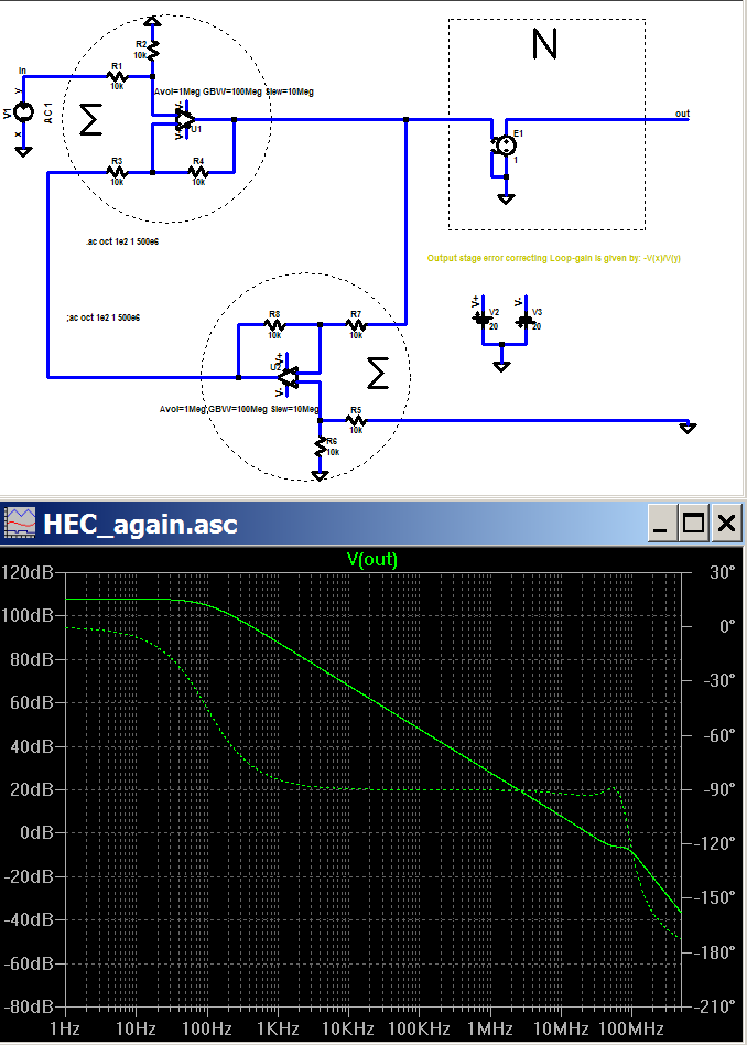
the amplifier open loop gain closely follows my earlier return difference loop gain plot of the closed loop amplifier at high gain where they are expected to be the same, the differences at low loop gain are expected due to the difference of open/closed loop (and +/- inputs have slighty different transfer functions in this circuit)
using positive feedback to cancel a local negative feedback in order to peak a circuit gain is so old that it goes beyond "traditional" and is now "ancient history" and has fallen out of practice/teaching curricula; see "regeneration" - Armstrong and de Forest patent fight over its invention went to the Supreme Court
I believe a confusion is your misapplication of the concept of "opening/disabling the negative feedback loop to see the open loop gain" to the EC circuit
as I just pointed out on the previous page there are multiple loop signals in some branches of the EC circuit, your chosen point disables both positive and negative feedback loops - since the open loop gain depends on the positive feedback you have simultaneously disabled what you purport to measure
try just disconnecting the negative feedback:
the amplifier open loop gain closely follows my earlier return difference loop gain plot of the closed loop amplifier at high gain where they are expected to be the same, the differences at low loop gain are expected due to the difference of open/closed loop (and +/- inputs have slighty different transfer functions in this circuit)
traderbam said:[B[snip]Yes we do...so please listen. The loop gain at C is ALWAYS the correct NFB loop gain, regardless of switch position. With the switch in the upper position the loop gain at A or B is no longer the NFB loop alone, it now includes the nested PFB loop, so it is not valid.[snip][/B]
Sorry, but it seems self-evident from simple inspection of the circuit that switching does not in any way change the loop going through either A or B. In either switch position, the loop gain in A or B is a result of both the pos fb part as well as the neg fb part. Only the loop gain at C changes with the switch position because with the switch up it no longer includes the pos fb part but only the neg fb part.
That indeed is the crux of our discussion.
If we built this circuit in a black box, there is no way from measuring the amp I/O transfer curve to find out in which position the switch is. Measuring the loop gain at C DOES give a clear indication of the switch position, because that measurement is different in each switch position. But since the switch position doesn NOT change the amp transfer curve, it seems a logical contradiction to consider the loop gain at C as the correct loop gain measurement.
Jan Didden
Edmond Stuart said:
Hi Jan,
You are right. I'm sorry I've overlooked that. On the other hand, you changed to a complete different scheme that has little to do with Hawksford EC. Not the most obvious way to clarify our different points of view. 😀
Cheers, Edmond.
Not at all! My circuit is exactly the conceptual approach from Hawksford with b=0, a=1. In these types of discussions it is often necessary to try to dig down to the very fundament and toss out everything that is not essential, like a and b. Once the fundament is thoroughly understood, implementation becomes straightforward.
In the sim circuit you send me, the N^-1 input to the error summer is at the emitters of Q52,54 (through the 27 ohms resistors). The -1 input is at their bases through the resistor network, attenuated. Actually, it is a +1 term that is later inverted at the collectors.
Jan Didden
Jan wrote:
There is no contradiction at all. Why do you assume that the because the transfer function does not change that the feedback cannot be changing?But since the switch position doesn NOT change the amp transfer curve, it seems a logical contradiction to consider the loop gain at C as the correct loop gain measurement.
Infinite Gain is a Mathematical Abstraction
Interesting, I had a feeling that those who claimed that HEC was just another view of NFB would require some non-realizable function. Sure enough your suggesting that it is possible to design infinite gain into a real world design? I don't think so, not even close at HF.
So, yes, I have a problem with this, a null in HEC is a physically realizable design, within reason, as has been proven by Bob's and several other designs.
Now come on, infinite gain is a mathematical abstraction and you expect me to take this as an example of a real world design?
Again, let me offer the challenge, show me a physically realizable design using traditional NFB with a null pot.
I'm sure you understand that there are implementation details to consider here.
Pete B.
Edmond Stuart said:
Hi Pete,
......
If the NFB loop gain approaches infinity, then the distortion drops to almost 'null'
Cheers, Edmond.
Interesting, I had a feeling that those who claimed that HEC was just another view of NFB would require some non-realizable function. Sure enough your suggesting that it is possible to design infinite gain into a real world design? I don't think so, not even close at HF.
So, yes, I have a problem with this, a null in HEC is a physically realizable design, within reason, as has been proven by Bob's and several other designs.
Now come on, infinite gain is a mathematical abstraction and you expect me to take this as an example of a real world design?
Again, let me offer the challenge, show me a physically realizable design using traditional NFB with a null pot.
I'm sure you understand that there are implementation details to consider here.
Pete B.
If it is so Obviously NFB, Show us a Design
traderbam you have suggested so many times that your viewpoint is so obvious, and so correct. Let me ask you, show me a traditional NFB design with a null pot that is physically realizable.
Do you have a design of your own to offer, I only ask because you suggest that this is all so simple.
I'm sure you understand that there are implementation details to consider here.
Pete B.
traderbam said:Thanks for supporting my argument, Edmond. I'll have to apply some ice to my forehead.🙂
traderbam you have suggested so many times that your viewpoint is so obvious, and so correct. Let me ask you, show me a traditional NFB design with a null pot that is physically realizable.
Do you have a design of your own to offer, I only ask because you suggest that this is all so simple.
I'm sure you understand that there are implementation details to consider here.
Pete B.
PB2 wrote:
Hi Pete. I don't know of any. I don't know why anyone would want one.traderbam you have suggested so many times that your viewpoint is so obvious, and so correct. Let me ask you, show me a traditional NFB design with a null pot that is physically realizable.
PB2 wrote:
What are you claiming has been proven? Bob's design reduces the error by 30db at 20kHz. There is no null in the sense of eliminating errors.So, yes, I have a problem with this, a null in HEC is a physically realizable design, within reason, as has been proven by Bob's and several other designs.
EC
Hi Pete,
I said approaches infinity, not is infinity, meaning in real life that a max. NFB loop gain in a HEC circuit of say 60dB is realizable. As a result, the distortion will approach zero, but never exactly zero.
As for Bob's design, what do you mean: exactly zero or almost zero?
Cheers, Edmond.
jcx said:Pete,
using positive feedback to cancel a local negative feedback in order to peak a circuit gain is so old that it goes beyond "traditional" and is now "ancient history" and has fallen out of practice/teaching curricula; see "regeneration" - Armstrong and de Forest patent fight over its invention went to the Supreme Court
Yes I know a bit about the history, oh great one:
http://www.diyaudio.com/forums/showthread.php?postid=1062575#post1062575
jcx said:
I believe a confusion is your misapplication of the concept of "opening/disabling the negative feedback loop to see the open loop gain" to the EC circuit
Confusion, no I understand the circuit just fine thank you, as I explained way back here:
http://www.diyaudio.com/forums/showthread.php?postid=1063589#post1063589
What I find interesting is that generally when we speak of gain in an amplifier circuit we are talking about the gain seen by the signal that is being amplified. You've chosen to break the loop in such a way that you measure gain that is never actually seen by the signal being amplified. You may go ahead and do this, but be clear when you make claims and statements about what you are measuring. I'd say that you've significantly altered the operation of the circuit. For example you could never measure that high gain in the circuit when operating normally. Yes it is interesting from a theoretical perspective.
jcx said:
as I just pointed out on the previous page there are multiple loop signals in some branches of the EC circuit, your chosen point disables both positive and negative feedback loops - since the open loop gain depends on the positive feedback you have simultaneously disabled what you purport to measure
Yes, when I open the loop I choose to open both paths because it best illustrates how the circuit produces the correction signal in normal operation and what is actually fed back to the first summer. Why is opening just one loop valid, because it proves some abstract point that you are trying to make, which, while technically interesting has little relation to how the circuit actually works.
I'm going to drop out here, I thought my points were obvious, it seems that some of the intellectuals here are taking a very abstract view simply to show how abstract they can get in their thinking.
Pete B.
EC
Hi Jan,
Although the final result may be the same, i.e. (almost) zero distortion, that does not imply that the conceptual approach is equal.
Further, the signal at the input of the error summer is not N^-1, but 1-N. That makes a big difference, sorry.
Cheers, Edmond.
janneman said:Not at all! My circuit is exactly the conceptual approach from Hawksford with b=0, a=1.
...................
In the sim circuit you send me, the N^-1 input to the error summer is at the emitters of Q52,54 (through the 27 ohms resistors). The -1 input is at their bases through the resistor network, attenuated. Actually, it is a +1 term that is later inverted at the collectors.
Hi Jan,
Although the final result may be the same, i.e. (almost) zero distortion, that does not imply that the conceptual approach is equal.
Further, the signal at the input of the error summer is not N^-1, but 1-N. That makes a big difference, sorry.
Cheers, Edmond.
A long time ago ...
More precisely post 795 11/24/2006 I posted a side by side abstraction of cannonical GNF and EG as applied to real world situations, in the sense the blocks can decently be replaced by actual electronic modules.
Judging from the discussion still going on, perhaps it could help a refresh, and of course a founded critique. Conclusions should be quite stightforward, but may be further elaborated if needed be.
Rodolfo
By the way, nice work Rodolfo.
My, hopefully last word on this, here's how I see it. Several bright minds noticed a way to improve amplifier output stages by using a new form of local feedback. It was published, designs were built where the distortion fell to near or below the noise floor. It addressed a problem in that with most traditional NFB designs distortion rises with increasing frequency. Is it the only solution? No, is it a good one, yes it is in my opinion. The implementation is certainly different as compared to traditional NFB designs.
I don't see how intellectuals can view it as reasonable to reduce the design to a block diagram, apply some theoretical transformations and claim that it is just negative feedback. Indeed, the implementation is not "just" negative feedback, in fact they view it as using positive feedback even when I point out that it nulls in normal operation.
The difference is in the implementation, people who loose site of this fail to recognize part of the engineering challenge which is to actually design something that can be built.
There is a case of NIH going on here in my opinion:
http://en.wikipedia.org/wiki/Not_Invented_Here
Pete B.
PB2 said:......
The difference is in the implementation, people who loose site of this fail to recognize part of the engineering challenge which is to actually design something that can be built.
...
Sure Pete, and this is the interesting part which otherwise could go unattended.
As I see it, the challenge lies in implementing a summing node as close to ideal as possible.
This implies on one hand, an as precise as attainable 1/S - B = 0. For DC, this depends in the analog world gain adjustment (Bob's magic pot which I "discovered" a couple of years back - nth instance and counting), and in the digital world hangs on A/D error and math precision.
On the other hand, since 1/S is a complex mangitude, then summing node bandwidth should be orders of magnitude larger than working bandwidth for this scheme to work, for this ratio is - to say in one possible way - approximately the effective distortion attenuation.
Lastly, gain and phase margin for the whole system must satisfy the usual stability requirements, which are no worse than conventional GNF with very large OL gain.
Rodolfo
- Home
- Amplifiers
- Solid State
- Bob Cordell Interview: Error Correction