jcx wrote:
Not with you here. A PFB loop should be capable of any gain you desire within the constrains of stability. The summer gains are only 1, ideally. Or are you talking about something else?this means that EC gain is strictly limited by the gain of the circuits implementing the summers
Ideal EC analysis
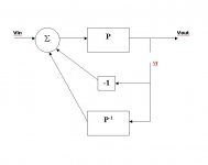
Earlier Jan and I agreed that the attached disgram represents perfect error correction. And I think it is Jan's premise that HEC is equivalent to this. It is my conjecture that HEC can achieve the same behaviour only with infinite NFB. So I want to show how NFB is measured in each case.
To measure the NFB we measure the loop gain around the output node. It can be measured at some other points, but this point is handy. I've broken the feedback line and replaced Vout with Vf as the feedback signal. The NFB loop gain is -Vout/Vf. I'm making the simplifying assumption that Vin=0.
Vout = P{ -Vf + P*{Vf} }
This cannot be reduced further because P is an arbitrary, non-linear function. However, we can choose a selection of linear values of P to see how the gain changes with P.
Let's suppose P{x} = k.x, this gives -Vout/Vf = (k - 1)
If k=1 the NFB gain is zero. There is no feedback. When k = 2, the NFB gain is 1, and so on. The amount of feedback depends on the value of P and it is finite. When k is near to 1 there is perfect error correction with very low NFB gain.
Now, let's do the same with HEC:
Vout = N{ a.Vf /(a - 1) }
For "null" it is a requirement that a=1. This makes the input to N{} infinite, regardless of what N is. So if N has non-zero gain, linear or otherwise, the NFB loop gain is infinite.
Here is a stark comparison of two systems that both, mathmatically, perfectly correct the gain block P or N. However, one uses finite feedback that reduces with error and the other uses infinite feedback at all times.
The bottom line is that it is impossible to create an inverse of a non-linear function using only linear components in the feedback path without implementing an infinite NFB loop (which is impossible in practice due to stability constraints).
Bob's output stage doesn't implement perfect HEC as we have seen. It limits the NFB gain to 30dB...50db or so and rolls the gains off to keep the stage from oscillating. And further requires an output inductor to mitigate reactive loads. Generating NFB gain using PFB is a very neat approach but you don't get something for nothing.
Attachments
It is possible to create almost anything from the ideal blocks 😉 . It is the real circuit implementation, experiment and proof that make a great design.
traderbam said:Ok, good. Your single block with N-1 is fine. You are absolutely right that this arrangement completely eliminates the output error. This is the block diagram that you really want to be able to build in a real circuit, right?
Now, do you consider the system to involve feedback from the output? I think you do. If so, how would you determine how much feedback there is?
Yes of course I want to build it, in fact have done so already. Brian, I'm not out to win an argumment, I really would like to fully see through this. So please bear with me.
In the attached, do you agree that we can break the loop anywhere, like at A, B or C, measure the loop gain and always measure the correct (and always the same) value?
Jan Didden
Attachments
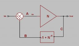
Yes.In the attached, do you agree that we can break the loop anywhere, like at A, B or C, measure the loop gain and always measure the correct (and always the same) value?


If you mean Vout/Vin then yes. The switch position does not affect Vout/Vin, in mathmatical operation, and Vout/Vin=1 is the only solution.
OK, we are getting closer. This is what I am grappling with:
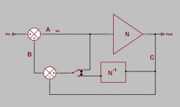
With the switch in the lower position, we can break the loop at A, B or C, always measuring the same value for the loop gain. Obviously, when we put the switch in the upper position, the loop gain measurements at A and B will not change, but at C will, because we now measure a different 'loop' at C than before.
The transfer function from input to output doesn't change with the switch position. The loop gain doesn't change with the switch position. The loop gain measurement at A or B doesn't change with the switch postion. Thus the loop gain measurements at A, B give a correct value. That would mean that measuring the loop gain at C, with the switch in the upper position, is incorrect. Yet both you and jcx maintain it IS correct, and you guys obviously know what you are talking about.
So, where do I go wrong in my reasoning?
{It is what I meant earlier by saying that at A or B you mesasure the loop enclosing the 'effective feedback', I know, a non-standard term. The idea behind it is explained for example here:
http://www.linearaudio.nl/Documents/graeme feedback generalization.pdf .
There is also a paper by Cherry on nested feedback loops that uses the same concept, but I can't find that at the moment.}
Jan Didden
janneman said:OK, we are getting closer. This is what I am grappling with:
With the switch in the lower position, we can break the loop at A, B or C, always measuring the same value for the loop gain. Obviously, when we put the switch in the upper position, the loop gain measurements at A and B will not change, but at C will, because we now measure a different 'loop' at C than before.
The transfer function from input to output doesn't change with the switch position. The loop gain doesn't change with the switch position. The loop gain measurement at A or B doesn't change with the switch postion. Thus the loop gain measurements at A, B give a correct value. That would mean that measuring the loop gain at C, with the switch in the upper position, is incorrect. Yet both you and jcx maintain it IS correct, and you guys obviously know what you are talking about.
So, where do I go wrong in my reasoning?
{It is what I meant earlier by saying that at A or B you mesasure the loop enclosing the 'effective feedback', I know, a non-standard term. The idea behind it is explained for example here:
http://www.linearaudio.nl/Documents/graeme feedback generalization.pdf .
There is also a paper by Cherry on nested feedback loops that uses the same concept, but I can't find that at the moment.}
Jan Didden
I do not read every post here, and I am a bit surprised if the discussion here now applies to the disagreement that started back around post 555 as it would seem that people were talking about different problems. OK ... well ... I'm not surprised.
It is obvious to me that they are considering a different problem and this is why I asked the question above about jcx's simulation.
First off, this discussion is about the local feedback loop of the output stage alone, and therefore comments about loop stability as if it was the major loop make stability concerns seem more serious than the reality of good implementations such as Bob's. Indeed, Bob's real design works and is stable, yet some here are claiming such designs will not be stable.
Second, points A, and B would be a traditional measurement of the local loop gain. C (with your switch up) as in jcx's simulation is a measure of the differential error correction gain, for lack of a better term, since only one side of the null circuit is driven. It is indeed different than the major loop gain measurement and not what I've been talking about all along here.
I don't believe that with regard to the local loop gain (points A or B) this looks anything like traditional negative feedback, yes perhaps in an abstact way it is, but not for this particular implementation. What traditional negative feedback design has a null control?
jcx's simulation by way of demonstrating the null seems to counter the very claim of a direct mapping to traditional negative feedback.
I like to think of this as null derived predistortion. It should be easy to see this with the proper adjustments to jcx's simulation.
Pete B.
I modified jcx's simulation with a fixed 10K resistor so that it represents a properly nulled HEC design. It can be seen that the error term V1 has been removed from the output as V👍 (blue) in the plot below. V(va) (green) is a 1 V 20 kHz signal that is produced by the null summer, and V(v_predistort) (red) is the predistorted input to the output stage that is required to remove V1 from the main output v👍. Note that the null is not perfect since jcx's model approximates real world hardware by employing finite bandwidth summers. Still, it is an excellent approximation to the ideal mathematical model. This sim does not provide an input signal and I'll follow up with another sim that does.
http://baselaudiolabs.googlepages.com/hec_not_negfbD1.JPG
http://baselaudiolabs.googlepages.com/hec_not_negfb1.JPG
http://baselaudiolabs.googlepages.com/hec_not_negfbD1.JPG
http://baselaudiolabs.googlepages.com/hec_not_negfb1.JPG
Add an Input Signal
I added an input signal, 5 kHz 10V, larger and lower frequency to make the signal easy to see as compared to the 20 kHz 1V error signal. The schematic is given first below and some waveforms follow. It can be seen that the null summer produces only the required error signal (blue) and none of the main input signal, also the predistorted input to the output stage can be seen in red, and the corrected output in green.
http://baselaudiolabs.googlepages.com/hec_not_negfbD2.JPG
http://baselaudiolabs.googlepages.com/hec_not_negfb2.PNG
Attachments
Open the loop
Here I have opened the feedback loop by grounding the feedback input to the first summer. Note that the system gain does not change, it is unity with 10V in and 10V (plus distortion) out. The gain changes in traditional feedback systems when we open the loop. The circuit and waveforms are given below. It can be seen that the gain does not change, the output is now distorted obviously, and the feedback term V(va) is just the correction term with no signal. While some may claim that these can be mathematically transformed into traditional negative feedback systems, it is clear that real implementations are nothing like traditional negative feedback systems. Show me a traditional negative feedback system with a distortion null control.
http://baselaudiolabs.googlepages.com/hec_not_negfb3D.PNG
http://baselaudiolabs.googlepages.com/hec_not_negfb3.PNG
janneman said:.............
The transfer function from input to output doesn't change with the switch position. The loop gain doesn't change with the switch position. The loop gain measurement at A or B doesn't change with the switch postion. Thus the loop gain measurements at A, B give a correct value. That would mean that measuring the loop gain at C, with the switch in the upper position, is incorrect. Yet both you and jcx maintain it IS correct, and you guys obviously know what you are talking about.
So, where do I go wrong in my reasoning?
..................
[/B]
Hi Jan,
You say: "The transfer function from input to output doesn't change with the switch position." (I suppose you mean from Vin to Vout)
That's impossible. Different topologies have always different transfer functions, unless N = 1.
BTW, In that case the EC stage is totally ineffective and we don't need it at all. 🙂
Cheers, Edmond.
the gain (Bode's "return difference") measured in a single loop will be constant if properly measured at any point within that single loop
this property applies to all nested/multiple negative/positive feedback loops as well - but each loop will have a different return difference and some branches will contain signals for multiple loops
interpreting the significance of the return differences measured by cutting branches common to multiple loops isn't usually attempted
the EC circuit has 2 loops (ignoring the local loops inside my summer implementations), different gains are measured by test sources placed in the different loops
There are 4 logically different branches at which the loops can be "opened" for return difference testing, 3 different measurements result from cutting:
outer negative feedback loop (immediately adjacent to N)
inner positive feedback branch (U2 summer negative input)
or either of the 2 branches that are common to both loops(U1/2 summer outputs)
Edmond Stuart said:
Hi Jan,
You say: "The transfer function from input to output doesn't change with the switch position." (I suppose you mean from Vin to Vout)
That's impossible. Different topologies have always different transfer functions, unless N = 1.
BTW, In that case the EC stage is totally ineffective and we don't need it at all. 🙂
Cheers, Edmond.
Edmond,
Please note that the switch only selects a different point in the topology to pick off the N^-1 term. Since the two points are equivalent, indeed there's no change at all. In both cases the loop gain and thus the I/O transfer functions doesn't change.
The only thing the switch changes is the effect of breaking the loop at C.
Jan Didden
- Home
- Amplifiers
- Solid State
- Bob Cordell Interview: Error Correction