EC loop gain
Hi Jan
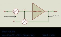
I'm spicing Bob's EC output stage and looking at the gain and phase of a couple of loops. To make sure that I also include your approach (see method A), please confirm that the loop has to be broken at that position, if not, correct me.
Cheers, Edmond.
Hi Jan
I'm spicing Bob's EC output stage and looking at the gain and phase of a couple of loops. To make sure that I also include your approach (see method A), please confirm that the loop has to be broken at that position, if not, correct me.
Cheers, Edmond.
Attachments
Re: EC loop gain
Yes method A. Appreciate it.
Jan Didden
Edmond Stuart said:Hi Jan
I'm spicing Bob's EC output stage and looking at the gain and phase of a couple of loops. To make sure that I also include your approach (see method A), please confirm that the loop has to be broken at that position, if not, correct me.
Cheers, Edmond.
Yes method A. Appreciate it.
Jan Didden
Jan wrote:
To say there is no feedback when N=1 is totally wrong. If a=1 then the feedback is inifnite no matter what scalar value N has.
I'm just saying the equation does not accurately represent the non-linear system.Now you seem to say that the math is illegal and it couldn't happen. If the a bothers you, delete the a, replace by a wire. Don't tell me that then Vx=Vy-N.Vy is illegal!
We're dealing with a PFB loop nested within a NFB loop. The nesting obscures the underlying behaviour.My point is that if you break the loop at x-y you end up with a loop gain of 1-N, which can only lead to pfb if N<1, but then the loop gain is too low to support any 'infinite gain'.
I was talking about 'a' not 'N' and its effect on the feedback loop from the output. When 'N' = 1 there is loads of feedback. Who cares what happens at Vx? Your error is that you keep ignoring the feedback path that matters: that is the path coming from the output node; the node you are trying to control.You also said earlier: if N>1 it's nfb, with N<1 its pfb, with N=1 its infinite gain. I agree with 2 out of 3. The math as well as practise shows clearly that when N=1 there's no fb at all because Vx=Vy.
To say there is no feedback when N=1 is totally wrong. If a=1 then the feedback is inifnite no matter what scalar value N has.
Zen and the art of feedback
Jan, just because the correction signal at the input summer is zero does not imply there is no feedback.
Jan, just because the correction signal at the input summer is zero does not imply there is no feedback.
traderbam said:Bob,
There ought to be a permanent thread entitled "measuring sound quality".
In my flippant remark I didn't mean to say that all measurements are poor. Of course there are lots of very sophisticated measurements of specific things, like THD and TIM and slew rate and so on, that are very good as measurments. What I have observed is that each time a new measure is invented there is a big design effort to optimise that measure and you get a bunch of new products being reviewed in Stereophile. However, the correlation between these new products and improved sound quality is loose, in general. The measures are not hitting the nail on the head.
What do you think?
Correct on all counts.
There are many dimentions to this dilemma. We all would love to come up with that silver bullet measurement that would correlate with sound quality better, and the search for that is a very legitimate endeavor. But it is littered with past failures that have sent audio designers off in random directions based on wrong theories to begin with, or wrong interpretations of test results, or whatever. Not only have there been serious problems within the pure objective measurement realm, but the whole thing is severely exacerbated by the difficulty and psychology associated with listening tests.
There is at least a bit of a silver lining to this. When somebody comes up with a new test, the ensuing discussion and argument puts a spotlight on things, and we often all learn from it, even if the final outcome is that the test and its implications were wrong in some way.
Otala's work on TIM was a classic example of this. He claimed that high values of negative feedback and small open-loop bandwidth caused TIM. That sparked lots of discussion and argument. He then came up with his DIM test to measure TIM. That was a good thing, but it was also his undoing. When real amplifiers with high NFB and low open-loop bandwidth were measured with Otala's own test, they were shown to usually have LESS TIM than without feedback.
However, as flawed as the TIM concept was in regard to NFB, the debate largely resulted in better amplifier designs and a better understanding of many issues. The better amplifier designs were not better because they used low or no NFB, but they were better because of the spotlight cast on slew rate and high-frequency nonlinearity issues.
The negative part of the legacy is that NFB got an undeserved black eye, which lives on to this day in the minds of some designers. Their well-intentioned, but mis-directed, efforts at eliminating NFB have sometimes resulted in amplifiers that sound different because they are unfaithful to the sound in some way. Many people can easily confuse sounding different with sounding better or sounding more faithful.
Cheers,
Bob
Re: Zen and the art of feedback
Adding zero to Vin doesn't make a difference. How can there then be fb if the connection doesn't make a difference 😕 .
Jan Didden
traderbam said:Jan, just because the correction signal at the input summer is zero does not imply there is no feedback.
Adding zero to Vin doesn't make a difference. How can there then be fb if the connection doesn't make a difference 😕 .
Jan Didden
traderbam said:[snip] Your error is that you keep ignoring the feedback path that matters: that is the path coming from the output node; the node you are trying to control.[snip]
But Brian, both the fb from the input as well as the output of N, both control the output, because they both are making up the feedback error signal that gets back to the input to adjust the output. Why single out just the nfb part of the feedback loop? Doesn't the pos fb path also control Vout? Why then NOT break it if you want to break the loop?
Or else replace the unity error summer with a single block saying '(1/N)-1', connected with its input to Vout and output to a. Then you can cut the connection between Vout and that error summer input.
Jan Didden
Re: Re: EC loop gain
Hi Jan,
First, isn't it funny that this debate is going on for almost a year (starting at post #555), and yet we still disagree.
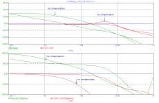
I've spiced Bob's EC output stage, with and without frequency compensation in the EC-stage, and I like to show you some graphs of the gain and phase response of the two different approaches. The red curves applies to your method, i.e. the loop broken at the input summer. The green curves applies to Brian's and my method, i.e. the loop broken at the output summer.
With the frequency compensation enabled, the system is stable, which is clearly predicted by the green curves, revealing a Ft of 3Mhz and a sound phase margin of near 90 deg. However, the red curves don't give us any clue at this frequency.
Without frequency compensation the step response is ringing and tends to oscillate at around 19MHz. This is also nicely predicted by the green curves, as the phase margin is almost zero. Indeed, your approach does also reveal that something is happening at 19MHz: the gain rises from -3dB to -1dB and the phase drops to -180 deg. However, such figures are not alarming, at least to me, yet the system is unstable.
The red curves are completely wrong, for the correct curves, see:
http://www.diyaudio.com/forums/showthread.php?postid=1307435#post1307435
Comments invited.
Cheers, Edmond.
janneman said:Yes method A. Appreciate it.
Jan Didden
Hi Jan,
First, isn't it funny that this debate is going on for almost a year (starting at post #555), and yet we still disagree.
I've spiced Bob's EC output stage, with and without frequency compensation in the EC-stage, and I like to show you some graphs of the gain and phase response of the two different approaches. The red curves applies to your method, i.e. the loop broken at the input summer. The green curves applies to Brian's and my method, i.e. the loop broken at the output summer.
With the frequency compensation enabled, the system is stable, which is clearly predicted by the green curves, revealing a Ft of 3Mhz and a sound phase margin of near 90 deg. However, the red curves don't give us any clue at this frequency.
Without frequency compensation the step response is ringing and tends to oscillate at around 19MHz. This is also nicely predicted by the green curves, as the phase margin is almost zero. Indeed, your approach does also reveal that something is happening at 19MHz: the gain rises from -3dB to -1dB and the phase drops to -180 deg. However, such figures are not alarming, at least to me, yet the system is unstable.
The red curves are completely wrong, for the correct curves, see:
http://www.diyaudio.com/forums/showthread.php?postid=1307435#post1307435
Comments invited.
Cheers, Edmond.
Attachments
Jan wrote:
It's as if you have it in your head that the signal that ends up at the input node is meaningful. This is not feed-forward in reverse! You are not adding a correction to the input in that way. No, no. You are trying to correct the output, not the input! That's why the output node is where you must break the loop.
Feed-back is not feed-forward in reverse!
No, no, no, no. The PFB loop doesn't control anything. You are fixated in the input summing node as being something to do with measuring the amount of feedback.But Brian, both the fb from the input as well as the output of N, both control the output, because they both are making up the feedback error signal that gets back to the input to adjust the output. Why single out just the nfb part of the feedback loop? Doesn't the pos fb path also control Vout? Why then NOT break it if you want to break the loop?
It's as if you have it in your head that the signal that ends up at the input node is meaningful. This is not feed-forward in reverse! You are not adding a correction to the input in that way. No, no. You are trying to correct the output, not the input! That's why the output node is where you must break the loop.
No, no,no. This is feedforward in reverse. And 1/N is not the inverse of N because N is a non-linear function.Or else replace the unity error summer with a single block saying '(1/N)-1', connected with its input to Vout and output to a. Then you can cut the connection between Vout and that error summer input.
Feed-back is not feed-forward in reverse!
Edmond,
A couple of observations right of the bat.
Firstly, the 19MHz thing in 'my' method doesn't surprise me (not the freq, but that it is there, I mean). Surely, whatever methos is used, there is bound to be some phase shift occuring at higher freqs leading to ringing. I don't think anybody ever claimed that H.EC was free of that.
Secondly, I see no sign of infinite loop gain. Indeed, the loop gain (if I interpret the graphs correctly, please correct me if I seem to be off here) appears to be just below unity. That does surprise me, as I had expected it to be just above unity.
Could I have a look at your circuit for this sim?
Jan Didden
I think it has been pointed out a few times that a,b,N are not constants but rather frequency dependent transfer functions a(jω), b(jω), N(jω)
further Bob's error correction has b(jω)=0
for real circuit components the transfer functions have at least 2 more poles than zeros
for the power output Emitter/Source Follower N(jω) and the error correction gain a(jω) the circuits will be unity gain (or low constant gain)
these "unity/constant gain" circuits have local negative feedback with limited open loop DC and low pass gain characteristics
with these real world limits 1 - a(jω) = 0 can only happen at one point/frequency at best
I'm pretty sure that it was shown earlier in this thread that when you work out the error correction positive feedback with realistic a(jω) you find that the open loop gain of a(jω) becomes available as classic negative feedback loop gain around N - it looks like the postive feeback loop has canceled the local negative feedback of a(jω)
1/N(jω) cannot be implemented even with perfectly linear N, it can only be aproximated over a restricted frequency range since any compensation circuit also has to have excess poles and cannot cancel the excess poles of N(jω)
Bob Cordell said:
Otala's work on TIM was a classic example of this. He claimed that high values of negative feedback and small open-loop bandwidth caused TIM. That sparked lots of discussion and argument. He then came up with his DIM test to measure TIM. That was a good thing, but it was also his undoing. When real amplifiers with high NFB and low open-loop bandwidth were measured with Otala's own test, they were shown to usually have LESS TIM than without feedback.
BTW, the famous Electrocompaniet flaws in FFT analysis - to high content of high order harmonics.
Attachments
traderbam said:[snip]You are trying to correct the output, not the input! That's why the output node is where you must break the loop.
[snip]
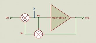
No, we are measuring LOOP GAIN. So we can break the loop anywhere we want, surely the loop gain is the same everywhere in the loop, as long as you enclose the whole loop (and that is where we view things differently).
Your assertment that we try to correct the output and that therefore only the direct feedback from the output is part of the loop is incorrect. You take a sample of the output and feed that back to the input. It is the size and shape of that sample that determines what happens. You can take it directly from the output, or through an attenuator like in beta-feedback. You don't make the point that because you want to correct Vout, you can't take the output from an attenuator instead of Vout, do you?
You can break the loop at point X in the attachement. What's your loop gain then?
Jan Didden
Attachments
jcx said:I think it has been pointed out a few times that a,b,N are not costants but rather frequency dependent transfer functions a(jω), b(jω), N(j&omega)
further Bob's error correction has b(j&omega)=0
for real circuit components the transfer functions have at least 2 more poles than zeros
for the power output Emitter/Source Follower N(jω) and the error correction gain a(jω) the circuits will be unity gain (or low constant gain)
these "unity/constant gain" circuits have local negative feedback with limited open loop DC and low pass gain characteristics
with these real world limits 1 - a(jω) = 0 can only happen at one point/frequency at best
I'm pretty sure that it was shown earlier in this thread that when you work out the error correction positive feedback with realistic a(jω) you find that the open loop gain of a becomes available as classic negative feedback loop gain
1/N(jω) cannot be implemented even with perfectly linear N, it can only be aproximated over a restricted frequency range since any compensation circuit also has to have excess poles and cannot cancel the excess poles of N(j&omega)
jcx,
Yes it waspointed out to me by Ed Cherry long time ago in a private communication that this type of circuit is a null network and therefore the correction is quite dependent on the freq response of the individual components. Indeed, a true null can - at best - be reached over a limited freq range.
What interest me is how far this can be pushed, and it is interesting to see that you (or I, I should say) end up with similar limits in linearity as 'normal' feedback.
BTW, a question on your assertion that 1/N(j&omega) cannot be approximated . Isn't the signal at the input of the N block exactly 1/N(j&omega) ?
Jan Didden
A true null can be achieved only at just one frequency, in case you have limited bandwidth.
But I guess it is all a little bit about nothing, as it gives no directions to amplifier design.
But I guess it is all a little bit about nothing, as it gives no directions to amplifier design.
jan, (turn off similies, keep the ";")
I am saying you cannot build a circuit with a transfer function identically equal to 1/N(jω) over all frequencies
negative feedback does create a "implicit inverse" signal at N(jω) input - but over a limited frequency range and with a limited (by open loop gain) accuracy
I am saying you cannot build a circuit with a transfer function identically equal to 1/N(jω) over all frequencies
negative feedback does create a "implicit inverse" signal at N(jω) input - but over a limited frequency range and with a limited (by open loop gain) accuracy
Coffee break
What am I going to do with you, Jan?
Time for a coffee break. I'm going to make a cup of coffee in a cafetiere. I bought a bag of Italian Lavazza beans and I'm gonna grind 'em up. I find the aroma of freshly ground bean most refreshing. Anyone fancy a cup?
What am I going to do with you, Jan?
No. You are measuring two loops at once. You must measure just the feedback loop from the output.So we can break the loop anywhere we want
I'll tell you what it is: it's irrelevant.You can break the loop at point X in the attachement. What's your loop gain then?
Time for a coffee break. I'm going to make a cup of coffee in a cafetiere. I bought a bag of Italian Lavazza beans and I'm gonna grind 'em up. I find the aroma of freshly ground bean most refreshing. Anyone fancy a cup?
Edmond,
I think I know why the red curve is just below 0dB instead of just above. IIRC Bob's ec circuit uses single transistors to extract the error. The error gain is less than one, while ideally it should be exactly one. if you would replace those transistors with an 'ideal' gain-of-one, the red curve should be just above one, in fact as much above one as the output stage gain is below one.
Jan Didden
janneman said:[snip]
.... I see no sign of infinite loop gain. Indeed, the loop gain (if I interpret the graphs correctly, please correct me if I seem to be off here) appears to be just below unity. That does surprise me, as I had expected it to be just above unity.
Could I have a look at your circuit for this sim?
Jan Didden
Hi Jan
I had already expected such questions. Look at 100kHz. The green curves show a gain of about +30dB. Indeed, it's not infinity. This is because Bob's circuit isn't perfectly balanced, the gain of EC circuit proper is slight below unity. If I increase R34 and R35 from 680R to 730R and looking at a frequency below where the gain starts to roll off, then I get 50dB. OK, it's still not infinity, but pretty high. 🙂
As for the schematics, I'll send them to you this evening. I have to leave now.
Cheers, Edmond.
Bob wrote:
I think one problem contributing to popular fear of NFB is that it is very complicated but has been applied casually like a band-aid in many cases, without enough consideration. Students tend to learn about feedback as part of basic op-amp theory and are shown that NFB makes several things better. But then they assume that it makes everything better. I start from the question "Why should NFB make anything better?".
Imagine if it were taught differently? Suppose the students were led outside to a field in which was a large, fit bull with an air of defiant independence. The students are told that a special mechanical device had been developed that when strapped to the beast would harness its energy and use that energy to control the bull itself. That the device would be fitted and then the bull would be given a swift kick in the oysters to make it really mad. Then the device would capture its rage and cause it to walk calmly in a straight line and stop and start on request and pull a cartload of china safely behind it.
Who would believe that?
Well said Bob. I grew up with this debate and I steadfastly refused to accept that NFB is bad for sound. That is not to say that I didn't witness and build circuits where the application of too much NFB made them sound pants. But I have resolved to clean up the bathwater rather than ditch the baby. I've figured out how to keep the bathwater drinkable now...took a long time. I'd say most low or no feedback designs sound better than most high feedback designs. I also believe that an expertly designed high feedback design should have no sound of its own, which is best of all.The negative part of the legacy is that NFB got an undeserved black eye, which lives on to this day in the minds of some designers. Their well-intentioned, but mis-directed, efforts at eliminating NFB have sometimes resulted in amplifiers that sound different because they are unfaithful to the sound in some way. Many people can easily confuse sounding different with sounding better or sounding more faithful.
I think one problem contributing to popular fear of NFB is that it is very complicated but has been applied casually like a band-aid in many cases, without enough consideration. Students tend to learn about feedback as part of basic op-amp theory and are shown that NFB makes several things better. But then they assume that it makes everything better. I start from the question "Why should NFB make anything better?".
Imagine if it were taught differently? Suppose the students were led outside to a field in which was a large, fit bull with an air of defiant independence. The students are told that a special mechanical device had been developed that when strapped to the beast would harness its energy and use that energy to control the bull itself. That the device would be fitted and then the bull would be given a swift kick in the oysters to make it really mad. Then the device would capture its rage and cause it to walk calmly in a straight line and stop and start on request and pull a cartload of china safely behind it.
Who would believe that?
- Home
- Amplifiers
- Solid State
- Bob Cordell Interview: Error Correction