traderbam said:The use of the word "null" really bugs me. What do people mean when they say this? I was taught that "null" meant reduce to zero or eliminate. But this is not what happens in a real feedback circuit of any topology.
I wonder too whether it is the behaviour of those resistors in a HEC-type circuit that leads to the use of this word: whereby if you make them variable there is a value where the output error is minimized, changing the resistance either side of this point increases the distortion. Well, this is a side-effect of the nesting of FB loops. Just because there is a minimum point on the pot doesn't in any way imply that this point is or should be a zero distortion point in a real circuit.
Why not try to look at it in a completely different way? In a NFB loop with device generated loop gain, the designer adjusts the gain and the compensation through simulation and experiment to some optimum point and then fixes the values. In HEC its like this was all done and then a pot was installed afterwards so that the circuit can be "de-optimised" at will. Either direction the pot is turned the performance is decreased.
You should study Philosophy, I minored in it by the way.
I *can* look at it in a different way, and I did, but I prefer the analysis that maps back to the actual real implementation.
I'm done here.
Pete B.
Jcx,
I admire your attempts to make things blatantly obvious, even though they aren't working.
One challenge is that some people are very good at believing what they want to believe and ignoring evidence to the contrary.
Another challenge is a seeming ignorance of how to measure feedback loop gain even though the method is universal.
I don't know how else to tackle this.
Brian
Nitpicking?? 😀 😀
Might it be more useful to analyze existing EC circuits or suggest new ones, that can be realized.
Might it be more useful to analyze existing EC circuits or suggest new ones, that can be realized.
traderbam said:The use of the word "null" really bugs me. What do people mean when they say this?
Says the man who claims this is all so obvious and simple and implies that the rest of us lack the intelligence to see your view. You don't understand null? Back to EE 101, or is it that you don't want to understand it because it demonstrates how you've lost sight of the actual implementation.
Show me a NFB design with a null pot, LOL!
Pete B.
Whatever, Pete, knock yourself out.
Have you measured the NFB loop gain of the HEC circuit? What did you find?
Have you measured the NFB loop gain of the HEC circuit? What did you find?
Edmond Stuart said:
To the best of knowledge, nobody has said that. But I'm convinced that EC has a negative influence on the stability margin. Why else would Bob say: "I think that one would have to be borderline suicidal to use this circuit without any output HF isolating inductor at all"
Cheers, Edmond.
I do recall saying that. Nothing is for free. As I have said many times over, Speed is King for the best operation of the EC circuit. This means that the local goings-on in the EC circuit will extend to higher frequencies, generally, than the global loop does. So, for example, where an unbuffered 0.01 uF capacitive load to ground on the output of an ordinary feedback amplifier with a gain crossover of 1 MHz or less might cause no problem, that same capacitor may cause some destabilization of the EC circuit, as that circuit will be working to well beyond 1 MHz locally.
Since only a 0.5 uH coil and a 0.5 ohm resistor were necessary to make my original EC amp unconditionally stable, and since even John Curl concedes that 0.5 uH is not a problem, I do believe that one would have to be crazy not to use at least that small amount of isolation in conjunction with an EC amplifier.
That is not the same as saying that the use of EC compromizes the stability of the global loop.
Cheers,
Bob
Bob Cordell said:I do recall saying that. Nothing is for free. As I have said many times over, Speed is King for the best operation of the EC circuit. This means that the local goings-on in the EC circuit will extend to higher frequencies, generally, than the global loop does. So, for example, where an unbuffered 0.01 uF capacitive load to ground on the output of an ordinary feedback amplifier with a gain crossover of 1 MHz or less might cause no problem, that same capacitor may cause some destabilization of the EC circuit, as that circuit will be working to well beyond 1 MHz locally.
Since only a 0.5 uH coil and a 0.5 ohm resistor were necessary to make my original EC amp unconditionally stable, and since even John Curl concedes that 0.5 uH is not a problem, I do believe that one would have to be crazy not to use at least that small amount of isolation in conjunction with an EC amplifier.
That is not the same as saying that the use of EC compromizes the stability of the global loop.
Cheers,
Bob
Hi Bob,
I'm happy you do agree with me.
BTW, 'compromising' doesn't mean the same as 'having a negative influence'. Besides, how else should I have called it, 'having a positive influence'?
Cheers, Edmond.
Re: Re: Open the loop
Forgive me for coming in late, as I am just trying to catch up,
but wouldn't the same be true if I moved global feedback from
the output of a follower stage to its input? The gain would remain
substantially the same, but the distortion would increase.
😎
janneman said:What I see is indeed that the gain stays substantially the same with only the distortion level changing dramatically. This is, as noted, completely different from a 'traditional' fb loop.
Forgive me for coming in late, as I am just trying to catch up,
but wouldn't the same be true if I moved global feedback from
the output of a follower stage to its input? The gain would remain
substantially the same, but the distortion would increase.
😎
traderbam said:
the crucial question as far as I am concerned is whether to use a synthetic block (a la HEC) to boost the OL gain of a unity gain follower output or whether to insert a normal gain block.
[/B]
Hi Brian,
Now you are beginning to ask the right question. As I have said many times, there are two or three equally valid ways of analyzing HEC. If you do the analysis right, they all come out the same. If you insist on using only the method of seeing the whole thing as a PFB that generates a lot of gain inside a NFB, then this is the right question to ask.
And I believe that the answer is that what you call the synthetic gain block made from unity gain PFB is resoundingly the very best choice for this application. If you try to realize this amazing piece of gain by conventional approaches, and have it be conveniently non-inverting, you may become very frustrated. The Devil is in the details, and the PFB approach to realizing this gain chunk is the key. Call it an implementation detail if you wish.
What you want here is a non-inverting gain element that will deliver perhaps 100 dB of gain down at very low frequencies and yet have extremely small excess phase out to well beyond 10 MHz. Not an easy chore for an op amp. This all, not to mention the differencing circuit you would still need.
Cheers,
Bob
I believe we still have an outstanding objection that no one has ever seen an amplifier with a (positive feedback) gain adjustment?
I hope this qualifies as "fair use" - from the MIT Radiation Lab V18 "Vacuum tube Amplifiers" (the pdf gives 174 text search hits for "positive feedback"):
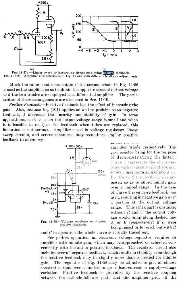
I hope this qualifies as "fair use" - from the MIT Radiation Lab V18 "Vacuum tube Amplifiers" (the pdf gives 174 text search hits for "positive feedback"):
I am sorry that I was not able to participate inthe discussions yesterday. I have the feeling that the focus has shifted. The focus was whether the breaking of *only* the neg feedback sub-loop of the H.EC circuit, and using that break point to measure loop gain, was the right way to do. I don't think it is. If indeed it isn't, we must re-evaluate the conclusion we drew from it.
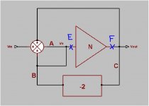
Let me back-up to the point where we agreed that measuring the loop gain at points A, B and C in the below circuit all gave the same and correct loop gain:
Jan Didden
Let me back-up to the point where we agreed that measuring the loop gain at points A, B and C in the below circuit all gave the same and correct loop gain:
Jan Didden
Attachments
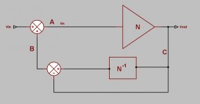
I now take this same circuit but with a switch where you can pick off a part of the feedback signal from two different point, without in any way changing the circuit transfer function.
It is self-evident that with the switch in the down position, measuring the loop gain at A, B or C again, as before, gives identical, correct, results. It is also evident that with the switch in the upper position, measuring the loop gain at C gives a different result. Since a circuit cannot have two different loop gains at the same time, at least one of the two measurements at C is incorrect. Which one?
We see that in either switch position, the loop gain measurements in A and B remain the same. We have also agreed earlier that at one position, all three equal measurements were the correct one. Therefore, the loop gain measured at C with the switch in the upper position is incorrect.
Jan Didden
Attachments

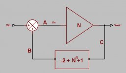
This circuit can again be rearranged without changing the circuit characteristics in any way as shown below.
Where, in this circuit, would you cut the loop to measure the circuit loop gain?
In this circuit each of the measurements in A, B or C would yield a different loop gain result. Again, a circuit can only have one loop gain at the time, so (some of) the measurements are wrong here.
Where, in this circuit, would you cut the loop to measure the circuit loop gain?
In this circuit each of the measurements in A, B or C would yield a different loop gain result. Again, a circuit can only have one loop gain at the time, so (some of) the measurements are wrong here.
Attachments
I can repeat this with different circuits ad nauseatum, in each case showing that breaking ONLY the one identified direct nfb connection from the output terminal to measure loop gain gives inconsistent results.
It appears we stumbled on a rule of the game that wasn't evident in this discussion, namely that if you want to measure the loop gain you must break the circuit in such a way that you break ALL separate feedback paths, positive or negative, at the same time.
If you do that, you can take any transformed configuration of a particular circuit and in each case come up with the same consistent loop gain result.
If you don't do it, you can have different incarnations of a circuit, all have identical transfer functions, with identical forward path elements, yet seemingly having different loop gains, and clearly this is not possible.
Jan Didden
Hi Jan, how are you doing today?
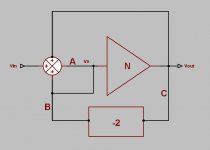
I would submit that the circuit does not have two different loop gains at the same time because the circuit is not the same. The transfer function, Vout/Vin, is the same but the feedback loop gain is different. This is because when the switch is down, the output error is nulled (truely nulled this time) by the inverse N block, so no feedback is needed. A sort of feedforward backwards. When the switch is up the inverse N block is replaced by a PFB loop and this creates an infinite feedback loop gain...this time reducing the output error to zero, if you will, rather than cancelling it.Since a circuit cannot have two different loop gains at the same time, at least one of the two measurements at C is incorrect. Which one?
At E or F. Again, the principle is to measure the gain in the single loop around the output device.Where, in this circuit, would you cut the loop to measure the circuit loop gain?
Attachments
What does this mean for the present discussion? It means you cannot break just the nfb part of the loop and say, see, it's pos feedback giving infinite gain. Of course that is true if you break only the nfb path. It is however NOT a correct characterisation of the circuit because the loop gain you measure is not correct, UNLESS you break ALL feedback loops at the same time.
Jan Didden
Jan Didden
traderbam said:Hi Jan, how are you doing today?
I would submit that the circuit does not have two different loop gains at the same time because the circuit is not the same. The transfer function, Vout/Vin, is the same but the feedback loop gain is different. This is because when the switch is down, the output error is nulled (truely nulled this time) by the inverse N block, so no feedback is needed. A sort of feedforward backwards. When the switch is up the inverse N block is replaced by a PFB loop and this creates an infinite feedback loop gain...this time reducing the output error to zero, if you will, rather than cancelling it.
At E or F. Again, the principle is to measure the gain in the single loop around the output device.
The circuit IS the same. The N^-1 block is a pfb loop, the same pfb value as taking it from N's input. If I built this in a black box, there's no measurement you can do to find out in what position the switch is. The same forward path elements, the same transfer function, measured and calculated.
Can you show me two circuits that have the same forward path elements and the same transfer function but different loop gains?
PS I'm hungry and need coffee. I think I'll settle for some Illy 😉
Jan Didden
I'm not sure what Illy is but I may have to have some cafeine too.
I'm going to need help with this, Jan. I see two distinctly different circuits. When you say the N^-1 block is a pfb loop...erm...how so? I agree that the value at the output of the N^-1 block is identical to the value at the input of the N block, by definition, but the loop gain doesn't care about values it cares about paths.
I agree that as a black box the system looks the same.
The circuit IS the same. The N^-1 block is a pfb loop, the same pfb value as taking it from N's input. If I built this in a black box, there's no measurement you can do to find out in what position the switch is. The same forward path elements, the same transfer function, measured and calculated.
I'm going to need help with this, Jan. I see two distinctly different circuits. When you say the N^-1 block is a pfb loop...erm...how so? I agree that the value at the output of the N^-1 block is identical to the value at the input of the N block, by definition, but the loop gain doesn't care about values it cares about paths.
I agree that as a black box the system looks the same.
- Home
- Amplifiers
- Solid State
- Bob Cordell Interview: Error Correction