Doing the same I've got some new heatsinks coming as well plus I'm gonna use that thick sil pad for them and the BFs. Plus brand new pcb. Then all resistors will be replaced with 1/2 Watts. Others are already new. Put in a higher rated trimmer in 2k instead of the 1k and also put a 3 watt resistor at the input end. But all other bits first before that.
Sorry Ken if your referring to my BKs no overheating just high output voltage with no load. Plus on switch on the transform makes a sort of boing noise. Other never has so in rush of current. It could be one of those or both psu caps faulty. Ripple ratted at nearly 5 amps so pretty darn high. So should not be getting that boing noise.
Anyhow it's a challenge but also bit well big headache ha ha. No paracetamol left plenty of morphine not much good for headaches ha ha. Think it's been around 3 weeks plus on it now cor. Should have been a two minute job.
Oh cats on steroids now possibly Irritable bowl Disease and blimey like I've got my old cat back taken over 2 years to get it sorted. So can relax now and crack on properly no worries.
J50/K135
Maybe but mine works (boths)
Now just need to do that battery charger inclosure...
Mines bigger ha ha ha
Maybe but mine works (boths)
Now just need to do that battery charger inclosure...
Last edited:
Sure glad to hear that your kitty is better ..
A good kitty can take the edge off of many of life's trials.
Cheers
A good kitty can take the edge off of many of life's trials.
Cheers
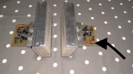
Cheers Rick sure relieves the stress for sure. Board stripped all I can say is there's quite a bit of track missing here and there and the resistors have just been bridged over to make contact. So not ideal. Just waiting on me new boards then can make up a new one. I'll also make some adjustments especially around the BFs and that resistor sitting bang in middle of all 4. The board has well overheated there again track not fully intact plus I'll make some of the tracks 2mm instead of 1mm with single 2mm solder circles along the 1mm paths.
Then there's room if need to install smaller components. Not sure why they did that. Sore good video on YouTube no ironing just acetone transfer image to glossy paper then stick over copper poor acetone on it rub really hard and vola ready for etching. Gotta be better than messing around with iron.
So it's obviously shorting out all over the place hence tapping components and your getting a good reading then back to square one. I think what's happened is it blew at some stage and the bent over lead outs looks like screw driver used to lift them obviously pulling off the track at same time.
Thats my analogy.

RS232 what spec have you done for the inductors?
Cheers Chris.
15 turns of 08 to 1mm magnet wire (is in the Maplin article)
Any update on your side ?
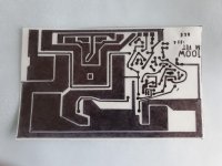
Thanks for that. Well I'm having trouble getting a good print of the board so I can etch a new one. Tried all these different programs but too complicated for me. So traced it out but again some of the traces are so thin that when you print it it bleeds over into the other track.
So bit frustrated with it at moment.
So bit frustrated with it at moment.
I’ll perceive with it. Got some quotes for clones well let’s just say rip you off job. I was a bit more blunt than that on the phone ha.
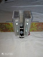
Looks like a rocket ha.
Looks like a rocket ha.
I used the picture from the board on the article and touched it up with "Paint" and had to print it several times to get the size right using the mosfet as reference and it worked quite well for me.
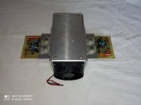
On my build I only bought the 1w and 3w resistor and the 3 capacitors everything else was scrap aluminium, scrap heatsinks fan came from a computer power supply even the cooper clad board were offcuts from previous projects, just a bit crossed because the battery charger enclosure is to small (not deep enough) to fit everything.
On my build I only bought the 1w and 3w resistor and the 3 capacitors everything else was scrap aluminium, scrap heatsinks fan came from a computer power supply even the cooper clad board were offcuts from previous projects, just a bit crossed because the battery charger enclosure is to small (not deep enough) to fit everything.
Done a good job since not really having to buy anything. Sure your work out battery scenario. Yeah definitely big heatsink. Blimey.
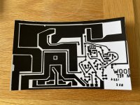
I traced the circuit out but of course where I've moved ruler you've got hairline streaks so if you over print say 4 times you lose some of the gaps in the tracks.
I traced the circuit out but of course where I've moved ruler you've got hairline streaks so if you over print say 4 times you lose some of the gaps in the tracks.
Attachments
Hi
Doesn't look bad for a hand made pattern.
You got me wrong, I did mine on the computer from a picture on the Maplin amp article and the "n" amount of times I had to print it was to get it up to real size because the original picture was smaller.
Doesn't look bad for a hand made pattern.
You got me wrong, I did mine on the computer from a picture on the Maplin amp article and the "n" amount of times I had to print it was to get it up to real size because the original picture was smaller.
Ah of course yeah can imagine not as easy as it looks especially from a picture. Lucky got board so traced it out even that took a while but managed to make the tracks slightly thicker so you can drill along it without losing the track itself. The original was like modern boards ultra small traces. Still can’t beat point to point wiring.
So .. RS232 .. You're saying that it DOESN'T fly ? 😉
Sorry, couldn't resist ..
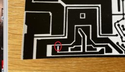
Shockhazard, that looks pretty good! Congrats on all that extra effort. There was one little place -- don't remember for sure -- is that spot in the red oval supposed to be connected?
Cheers
Sorry, couldn't resist ..
Shockhazard, that looks pretty good! Congrats on all that extra effort. There was one little place -- don't remember for sure -- is that spot in the red oval supposed to be connected?
Cheers
Attachments
- Home
- Amplifiers
- Solid State
- BK Electronics mosFET 100 watt modules