Member
Joined 2009
Paid Member
Very nice!
You want to keep Q3, Q4 and Q6 off the main heatsink. Unlike a regular EF output this CFP needs a different thermal control loop. The Vbe and two drivers can all be on a common heatsink but not the same one as the Output devices. I didn't find the drivers needed heatsinking, but you should have the Vbe (Q3) in thermal contact with at least one of the drivers. One way to do this without changing the pcb is to mount these devices standing up and then put a strip of metal across behind them, with insulator if the devices have metal packages, securing the devices to this common strip.
You want to keep Q3, Q4 and Q6 off the main heatsink. Unlike a regular EF output this CFP needs a different thermal control loop. The Vbe and two drivers can all be on a common heatsink but not the same one as the Output devices. I didn't find the drivers needed heatsinking, but you should have the Vbe (Q3) in thermal contact with at least one of the drivers. One way to do this without changing the pcb is to mount these devices standing up and then put a strip of metal across behind them, with insulator if the devices have metal packages, securing the devices to this common strip.
Member
Joined 2009
Paid Member
I'm just wondering about the ground routing. Do you see any benefit in an alternative ground connection quick fit lug over next to the output zobel? I thnk what you have is good, I just like to ask questions !
Are there any additional solder pads (with holes) you want to add so that you have some options to move or add parts in case of parasitic oscillations or even just to have some convenient places to rest a probe tip when checking operating voltages ?
Are there any additional solder pads (with holes) you want to add so that you have some options to move or add parts in case of parasitic oscillations or even just to have some convenient places to rest a probe tip when checking operating voltages ?
Last edited:
Hi Terry, you are too fast.
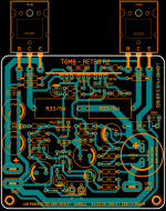
You didn't used last version on post#122 which was done base on Gareth pointers. All BD's are little back and close.
Any way you could mount drivers Q4 and Q6 and Vbe (Q3) on strip aluminium heatsink.
VR1 100k is use to adjust offset, in this case if you use 50v or 60v supply measurement will half at output,
eg: for 50v supply it should be 25v ( before 4700uF capacitor) .
VR2 is for bias.
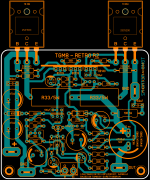
Latest version based on Gareth advice.
Regards
Sonal Kunal
You didn't used last version on post#122 which was done base on Gareth pointers. All BD's are little back and close.
Any way you could mount drivers Q4 and Q6 and Vbe (Q3) on strip aluminium heatsink.
VR1 100k is use to adjust offset, in this case if you use 50v or 60v supply measurement will half at output,
eg: for 50v supply it should be 25v ( before 4700uF capacitor) .
VR2 is for bias.
Latest version based on Gareth advice.
Regards
Sonal Kunal
Attachments
Last edited:
Member
Joined 2009
Paid Member
Looking good Terry - I do believe you are the person to have a chance at building as many amplifiers as Carlos DX !!
Sonal - looking good, now you have additional option, just in case. Never know what turns up once it's built. Part of the fun !
Sonal - looking good, now you have additional option, just in case. Never know what turns up once it's built. Part of the fun !
Hi Terry, you are too fast.
You didn't used last version on post#122 which was done base on Gareth pointers. All BD's are little back and close.
Any way you could mount drivers Q4 and Q6 and Vbe (Q3) on strip aluminium heatsink.
VR1 100k is use to adjust offset, in this case if you use 50v or 60v supply measurement will half at output,
eg: for 50v supply it should be 25v ( before 4700uF capacitor) .
VR2 is for bias.
Latest version based on Gareth advice.
Regards
Sonal Kunal
Actually this was etched using the sprint file from post #122. I did adjust things slightly so I could fit it on a 4" x 6.5" board. I didn't notice that the jpg was different than the sprint file. I won't have a problem fashioning a little heatsink for the drivers and vbe.
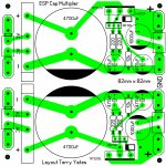
I plan to use a cap multiplier for the PSU and the rails should be about 46vdc.
Looking good Terry - I do believe you are the person to have a chance at building as many amplifiers as Carlos DX !!
Ha, I doubt I will ever build as many as he claims to have built. Hopefully I won't destroy as many as he claims to have destroyed either. 😀 I do enjoy keeping busy with it. 😉
Sorry, I was wrong, I etched them for the sprint file in post #119. I'll make it work. I should know tomorrow.
Hi guys
I finally got the pair of modules mounted in a nice chassis and all wired up, and I'm typing out this message from my armchair while listening to TGM8 single supply playing sweet music from a pair of nice floor standers.
I was kinda ambivalent about this project from the outset; the only capacitor-coupled amplifiers I've ever listened must be going on 30+ years, likely with their original, now dried out electrolytics. Needless to say I wasn't impressed then, and in the back of my mind I was expecting this one to not fare too well with its "old school" approach.
I couldn't have been more wrong, and I might as well say at once that its a match for Gareth's original. The sound is smooth, refined, detailed, without a hint of "muddiness" that I was half expecting, and that I know all too well from lesser amplifiers. Cymbals and other light percussion sound just right as do female vocals. I think the 22p miller cap is just about perfect (it passes a clean 20kHz square wave and the treble reproduction is credible) but I may experiment a little with the advanced compensation options I made provisions for.
If there is one criticism it might be that the bass doesn't have the same attack or impact in the lowest octaves as other designs... or it might be in my imagination. I'll drag out a bunch of amps including TGM8 original tomorrow and CSH5 (an "EF3 Blameless" that I haven't yet bested for gut-wrenching but beautifully controlled bass notes) and conduct some A-B testing.
I'm extremely happy with this amp - thanks everyone!
Hi
Can I suggest a small change, try to change the blocking capacitor to Philips axial type.
Way back many of us built the SEWA amplifier and that capacitor was the best choice to that place..
I prefer the older Philips type (not Vishay ) but they are very close sound wise. The Older Philips was a used capacitor (broken in) maybe that was the difference between the two..
http://partstore.langsungjadi.com/image/cache/data/Capacitor/Philips/philip2200uF_16v_d-800x600.jpg
So on an amp like this do the outputs only see half the rail voltage? Is that why you can use 60v with only one pair of outputs?
Outputs will see about 60v or less with 60v supply because of charging and discharging cycle of output capacitor when connected to load with signal applied.
Last edited:
I'm not sure if Ranchu is still following this thread, but looking at his speaker protection circuit, it appears that the added 100R resistors that he uses for charging the output will stay in circuit even after the relays engage. I'm not sure if having those in parallel with the speakers will make any difference but maybe one of you knows.
Usually there is no need speaker protection if there is DC blocking capacitor involved in the circuit.
Most of speaker protection badly degrade the achieved sound, even the best protection has some influence on it. My opinion, I do not argue over these.
If there is thump at start up maybe a soft starter would do the job.
At least I try to avoid to ad extra protection when there is no need for the mentioned reason.
I do tested several protection and yes to me it has more or less effect what I can hear..
Yes I agree when someone try to protect his expensive drivers but in these case the DC blocking cap will do the job.
The DC blocking cap is the problem here. It takes a few seconds to charge up during which time it allows almost 1/2 of the rail DC voltage to pass through to the speakers. Ranchu's fix is to allow they 100R resistors to help the cap charge up so by the time the speakers are switched on that process has completed.
The DC blocking cap is the problem here. It takes a few seconds to charge up during which time it allows almost 1/2 of the rail DC voltage to pass through to the speakers. Ranchu's fix is to allow they 100R resistors to help the cap charge up so by the time the speakers are switched on that process has completed.
It is possible, first time I read something like that
Very likely because the high rail voltage, 😱 I would test other type of caps there to. A few popular amplifier was built here just to mention some the Folks amp from Nelson Pass, SEWA , JUMA 25W cl. A amp with Lateral MOSFETs ... all Class A
The problem with the speakers protection the most of the time is on (the relay) and they do has effect on the sound
That is not mean the amplifier sound bad, I mean it would be better if there is no need for protection.
Last edited:
I forget to mention most of the times people use a smaller caps next to the 4700uF it maybe benefit from that
I'm not sure, need to be tested
I'm not sure, need to be tested
Member
Joined 2009
Paid Member
There is a trick to reduce turn-on thump here: MJR7-Mk5 Mosfet Power Amplifier Design Notes which uses a diode and some resistors - maybe an interesting option to explore ?
Very easy to start adding parts of course, like decoupling caps etc.
Very easy to start adding parts of course, like decoupling caps etc.
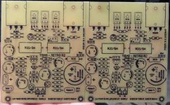
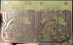
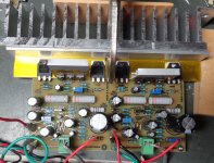
I have it singing. I'm using +46V rail. The center node is set to 23V. I don't know what the intended bias current is supposed to be. I set it to 35mv across one of the 0R33. I have only played for a few minutes. Just enough to make sure it would play. Sine and square waves look fine and it clips at about 13vac into 8ohms so about 21W output.
I can see the offset when I start up the amp bu I don't hear much of a thump.
I used NJW3281/1302 outputs.
Blessings, Terry
EDIT; I forgot to mention that I used SMD parts for the small capacitors. That is why you don't see them in the picture.
I can see the offset when I start up the amp bu I don't hear much of a thump.
I used NJW3281/1302 outputs.
Blessings, Terry
EDIT; I forgot to mention that I used SMD parts for the small capacitors. That is why you don't see them in the picture.
Attachments
Last edited:
Member
Joined 2009
Paid Member
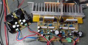
I have had a chance to listen to it at some length. It has a very pleasing sound. Later I'll try to hook it up to my A/B setup and see how it compares to other amps but I have really been enjoying listening to it this morning. There is really no noticeable turn on thump. That may be because I built a cap multiplier for the PSU. It has a ramp up in voltage so that may be giving the output cap time to charge up. There is only the slightest sound at switch on. The amp is dead quiet. I am bit surprised at how cool the amp runs even though I have the bias set to 110mA. I may have too large of heatsinks on the drivers too. They don't get even slightly warm so there is little chance that there is any thermal compensation happening. Very cool little amp! Thanks for the design guys.
Blessings, Terry
Blessings, Terry
Attachments
- Status
- Not open for further replies.
- Home
- Amplifiers
- Solid State
- Bigun's TGM8 with Single Supply