My boards arrived last week and I set to work assembling the first channel yesterday.
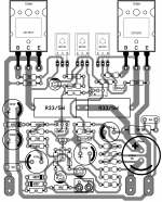
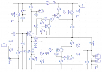
I noticed a small error on my last schematic, which had the output of the voltage divider used to bias the input transistor going to ground instead of Q1 base. Some minor board surgery and that's solved. R2 & R3 reduced to 10k to bias the output at ~Vrail / 2.
I noticed a small error on my last schematic, which had the output of the voltage divider used to bias the input transistor going to ground instead of Q1 base. Some minor board surgery and that's solved. R2 & R3 reduced to 10k to bias the output at ~Vrail / 2.
Attachments


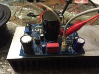
I should also add that it works nicely and plays music. I won't be able to say how good it sounds until I get into the living room. One thing I noticed is that it has a wicked turn on thump where the speaker terminal momentarily reads Vrail /2 as the output cap charges. I would not like to plug it into a quality loudspeaker without some sort of protection circuit; e.g. dummy load resistor followed by a speaker relay and delayed turn on circuit.
One of the great advantages I see with this topology is the ability to dispense with the DC protection circuit, so if there is a simpler way solve this problem I am all ears.
One of the great advantages I see with this topology is the ability to dispense with the DC protection circuit, so if there is a simpler way solve this problem I am all ears.
Member
Joined 2009
Paid Member
Ranchu32;4250634 One of the great advantages I see with this topology is the ability to dispense with the DC protection circuit said:MJR7-Mk5 Mosfet Power Amplifier Design Notes
"The only real problems with a capacitor coupled output are switch-on thumps as the capacitor charges through the speaker, some low level of capacitor distortion, and reduced low frequency damping factor. I included an anti-thump circuit, at the top left of the diagram, which consists of BAV20 diodes plus a resistor and capacitor. This reduces the switch-on pulse to about 1V, which makes just a small unobtrusive sound with my own speakers."
Hi guys
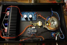
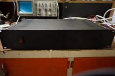
I finally got the pair of modules mounted in a nice chassis and all wired up, and I'm typing out this message from my armchair while listening to TGM8 single supply playing sweet music from a pair of nice floor standers.
I was kinda ambivalent about this project from the outset; the only capacitor-coupled amplifiers I've ever listened must be going on 30+ years, likely with their original, now dried out electrolytics. Needless to say I wasn't impressed then, and in the back of my mind I was expecting this one to not fare too well with its "old school" approach.
I couldn't have been more wrong, and I might as well say at once that its a match for Gareth's original. The sound is smooth, refined, detailed, without a hint of "muddiness" that I was half expecting, and that I know all too well from lesser amplifiers. Cymbals and other light percussion sound just right as do female vocals. I think the 22p miller cap is just about perfect (it passes a clean 20kHz square wave and the treble reproduction is credible) but I may experiment a little with the advanced compensation options I made provisions for.
If there is one criticism it might be that the bass doesn't have the same attack or impact in the lowest octaves as other designs... or it might be in my imagination. I'll drag out a bunch of amps including TGM8 original tomorrow and CSH5 (an "EF3 Blameless" that I haven't yet bested for gut-wrenching but beautifully controlled bass notes) and conduct some A-B testing.
I'm extremely happy with this amp - thanks everyone!
Member
Joined 2009
Paid Member
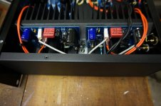
Here you go Gareth...
Ironically, I ended up using a speaker protection relay kit that I got from Ebay a while back to solve the start up thump. I thought about revising the design per the info you posted above, but this turned out to be the simple, cost effective, and expedient solution.
The power resistors you see are 100ohm wirewounds from speaker out to ground allow the coupling cap to charge up. The voltage drops below about 500mV after 10 seconds and then the protection circuit closes the relays.
Attachments

Member
Joined 2009
Paid Member
Thanks for building this.
My amp with the speaker capacitors, dynakit ST120, has never popped at turn on or turn off. I wonder what difference in design accounts for this?
I find reading the repair threads, speaker relays are 5 to 8 year devices before they often need removing and cleaning. So doing without one is one of the goals of my single supply amp. Your speaker relay board solves a problem, but injects another one. Unfortunately, restricting myself to western hemisphere made output transistors (ON TO3) which I've bought before they lay those guys off too, means I can't use your board for an "upgrade".
I found the ST120 modification with added closed loop bias control sounded really good for about 3000 hours, but the output transistor bias current sense circuit unmatched transistors for some reason.
Last edited:
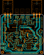
When this is a tested version, please share the bcb with us🙂Here my version of TGM8 single side pcb layout. I am confused which schematic I have to use, lots of version in this thread.
As far as whomp elimination at turn on, you could insert a 470 ohm resistor between the power rectifier and first rail capacitor, shorted by a relay after a few seconds. That should make the power supply creep up gently, and be a better use of a relay outside the sound path. Relays with copper or silver plate contacts work better with high energy sources to switch, instead of low energy music (most of the time). Or use a fet to short the charge up resistor, with resistor-capacitor to gate circuit for a timer. Make sure hold off voltage of the fet is higher than the vcc of the amp circuit.
Last edited:
Member
Joined 2009
Paid Member
Here my version of TGM8 single side pcb layout. I am confused which schematic I have to use, lots of version in this thread.
I like this layout, hope you are going to build this amplifier and report your listening impressions

- Status
- Not open for further replies.
- Home
- Amplifiers
- Solid State
- Bigun's TGM8 with Single Supply