@patrickblue Congratulations on the new house!
I'll get the yellow LED's. I have some BF861B's so I'll stick with the 47R R7 resistor.
Thanks again for your help.
I'll get the yellow LED's. I have some BF861B's so I'll stick with the 47R R7 resistor.
Thanks again for your help.
I have a minor problem with my BB3, so I am wondering if anybody has any ideas?
I have an intermittent buzz/hum which seems to be mains based.
It is a low frequency noise That I am trying to get rid of. I say it is mains based, as when I put my Power Inspired AG1500 mains regenerator in the power supply, the noise disappears.
So I am looking for a solution suitable to run a low power phono stage.
I have already replaced the main power regulator, and the mains input capacitors.
I am thinking of the diodes next.
Is there anything else I should do?
This is the noise in question:
Short version - 16 seconds - 3Mb - edited version
Realtime version - 3 minutes - 33Mb - Realtime version
Short version - 16 seconds - 3Mb - edited version
Realtime version - 3 minutes - 33Mb - Realtime version
I think I have sorted the problem.
Better attention to the earthing and AC power cables, and the hum seems to have gone.
Using Audacity, I managed to plot a frequency spectrum, and it was clear that it was indeed mains relate.
Link to plot.
A helpful steer on another forum, and it seems I have finally resolved my problem.
Better attention to the earthing and AC power cables, and the hum seems to have gone.
Using Audacity, I managed to plot a frequency spectrum, and it was clear that it was indeed mains relate.
Link to plot.
A helpful steer on another forum, and it seems I have finally resolved my problem.

Out of interest, is there any reason that the PCC88/7DJ8 cannot be replaced with 6n23p valves?
The 6n23p seems to be fairly rugged, and will often run happily at 7V.
I am just asking as the price of PCC88 valves seems to be getting rather silly.
The 6n23p seems to be fairly rugged, and will often run happily at 7V.
I am just asking as the price of PCC88 valves seems to be getting rather silly.
Shouldn't be a problem apart from valve life. It would be preferable to drop the voltage to 6.3 with an appropriate resistor.Out of interest, is there any reason that the PCC88/7DJ8 cannot be replaced with 6n23p valves?
The 6n23p seems to be fairly rugged, and will often run happily at 7V.
I am just asking as the price of PCC88 valves seems to be getting rather silly.
There is a mod involving 1N4148 diodes that drops the voltage to 6.3v suggested if I remember correctly by Craiglist earlier in the thread. I did this myself so that I could use ECC88/6922 valves. Will have to lift the lid on my build to remind myself exactly what needs doing.Out of interest, is there any reason that the PCC88/7DJ8 cannot be replaced with 6n23p valves?
The 6n23p seems to be fairly rugged, and will often run happily at 7V.
I am just asking as the price of PCC88 valves seems to be getting rather silly.
I vaguely remember that, but to my eternal shame couldn't be arsed to trawl through the thread to find it.
Thanks gents.
The reason I ask is that the spec sheets for the 6N23P state a 7V max for the heater voltage, so I could swap between PCC88 and the 6N23P at will. However, if valve life is an issue, it does not seem a good thing to do.
I have a few spare sets of PCC88 at the moment, so I have no immediate concerns.
I asked as the data sheet suggests a minimum voltage of 5.7V and maximum of 7V. https://frank.pocnet.net/sheets/112/6/6N23P.pdf
From the previous responses, I see that there is a mod to allow me to run the valves in V1 and V3 at 6.3V - if I need to. That won’t be for several years though.
From the previous responses, I see that there is a mod to allow me to run the valves in V1 and V3 at 6.3V - if I need to. That won’t be for several years though.
You are right insomuch as 7v is within spec, and a 6n23p will probably run quite happily at that. But it's also at the maximum of it's tolerance, and like anything, for instance a car engine constantly run at full revs, it's going to shorten it's life.
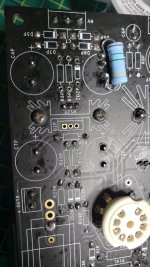
Hey, I'm not sure if anyone's still watching this thread, but I finally got around to building one of these with the multifet board.. Anyways, I got it all put together, and measured my voltages, and it was all exactly where it should be. Then I powered it off, and the next time I powered it up to give it a try I saw the magic smoke release from somewhere, and a bit of a spark from what appeared to be the C5 area... Super disappointing.
Anyways, I started measuring a few things and I noticed that when I measured ZD2P with the diode setting on my meter, it measured as a short in both directions, so that 12V zener definitely popped. I pulled out ZD2P, R5P and R6P since at first I noticed the really low resistance reading I got on those resistors (I assume now they must be in parallel or something with that Zener?).
You can see in the picture as well that I have also unsoldered a 1.5M resistor that I had in parallel with C5P (This was done to lower the B+ of the amp, as per some instruction from vivant earlier in the thread), and in the picture you can see I unsoldered it, and measured it out of circuit and it measures as it should.
Anyways, I'm kind of at a loss now as to what to do.. I'm nervous to just put another 12V zener in there, and put the resistors back in. Is it possible that the zener was just bad? Or would something else have likely caused it to pop? I'm also wondering if those 4 47uF caps in the power supply should be changed out as well..
I don't suppose Vivant is still watching this thread?
Attachments
I'd PM him. Vivant's probably the only one who could give you an answer, I'm like you, no idea where to start, plus it's so long since I built mine I can't remember much about it.I don't suppose Vivant is still watching this thread?
Hi, did you measure the zener in circuit and find a short? If so the FET Q1P is the likely culprit.
Yeah, it was shorted while in the circuit, and then after I pulled it out as well. I'll try changing out that FET then, and putting a new zener in.
Do you think anything else will have been damaged? Any idea what would have happened?
Do you think anything else will have been damaged? Any idea what would have happened?
Fair enough. I'm just putting a few new parts in to give it a try. Do you think maybe the FET itself was just faulty and failed?
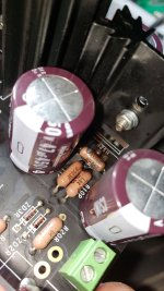
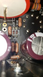
Well.. I put a new 12V zener in ZD2P, new resistors in R5P and R6P, and a new IRF820 in Q1P. Fired it up and it sparked right away. This time it left some burn marks on a few components.. It looks like R9P gave it up this time.. I attached some pictures of a very clear burn mark on that resistor specifically.. In circuit it's measuring 14 ohms now, not 390. What on earth could be going on with this thing? So frustrating..
Attachments
- Home
- Source & Line
- Analogue Source
- Bigbottle Phonostage Builders thread