Thanks for the input patrickblue and StevenCrook,
So I have been tracing the low voltage and here is what I have found out so far:
My LV going into the board is 9.5v ac, and 9.4v ac so I think I am good here. The voltage across the zenner diode is 59 - 57v dc. I have 60-69v dc across the 7805 which is not good. I'm not sure where to look between the LT input and the 7805.
Disconnected th HT. I get 12.5 - 5 across IC1P. I am getting 12.5 - 0 across R1P, and nothing across ZD1P.
As Flikoman said, some pictures would really help. I does sound as if the 7805 is open, with 12.5v going in pin 1, pin 3 should be giving 5v out.
I seems to me that there's HT getting into the LT circuit, how and why is another matter entirely.
I seems to me that there's HT getting into the LT circuit, how and why is another matter entirely.
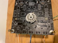
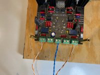
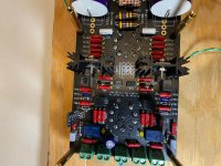
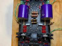
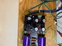
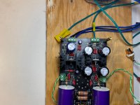
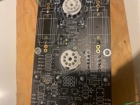
Pics for your review. Thank you again for helping out. I am really out of my depth here.
Attachments
-
 IMG_3131.jpg830 KB · Views: 206
 -
 IMG_3139.jpg767.5 KB · Views: 149
 -
 IMG_3138.jpg858.8 KB · Views: 165
 -
 IMG_3137.jpg807.8 KB · Views: 141
 -
 IMG_3136.jpg799.9 KB · Views: 138
 -
 IMG_3135.jpg811.9 KB · Views: 192
 -
 IMG_3134.jpg618 KB · Views: 189
 -
 IMG_3133.jpg788.5 KB · Views: 200
 -
 IMG_3132.jpg810.9 KB · Views: 190
Well, it all looks good in the photos. I would suggest you talk to Vivant.
I do know that the LT ground is around 55v higher than HT ground (Vivant said this earlier in the thread) so if you're measuring heater voltage against HT ground this may account for it. You need to be measuring heater voltage between pins 4 & 5 on V1 & V3 and 4 & 9 and 5 & 9 on V2 if it's jumpered for ECC83 or 4&5 if it's jumpered for 6NP2
Try that, and if as I suspect you get low to no voltage, try replacing the 7805 and the zenner.
That should give you 7v at V1&3 and 6.3 at V2.
Do all this with HT disconnected.
Also, make sure you are using a high quality 7805 with the thick mounting plate, the cheapo ones have caused no end of trouble.
Edit: The different ground potential is what made me think you were getting HT in the LT circuit, but measuring against a 55v lower ground is much more likely, and if that's the case the valves won't be damaged as I suggested earlier.
Last edited:

Try to replace 7805 regulator, I had problems with it aswel.
Relays must be soldered on TOP side.
Put some solder on the C8 capacitor, as BigMan suggested.
Disconnect HV when you try to power up the heaters. Get them to work first.
Relays must be soldered on TOP side.
Put some solder on the C8 capacitor, as BigMan suggested.
Disconnect HV when you try to power up the heaters. Get them to work first.
Ohh man, those relays are going to be a nightmare to desolder. thanks for the help so far everyone.
Slow and steady. Also, relays are cheap to buy. Last time I had to do something like this it was a block of dip switches. It became obvious I ran the risk of destroying the board trying to de-solder them. So I cut the body apart with a small pair of needle nose cutters. Then all I had to do was de-solder the pins. Still needs care of course...
Well, it all looks good in the photos. I would suggest you talk to Vivant.
I do know that the LT ground is around 55v higher than HT ground (Vivant said this earlier in the thread) so if you're measuring heater voltage against HT ground this may account for it. You need to be measuring heater voltage between pins 4 & 5 on V1 & V3 and 4 & 9 and 5 & 9 on V2 if it's jumpered for ECC83 or 4&5 if it's jumpered for 6NP2
Try that, and if as I suspect you get low to no voltage, try replacing the 7805 and the zenner.
That should give you 7v at V1&3 and 6.3 at V2.
Do all this with HT disconnected.
Also, make sure you are using a high quality 7805 with the thick mounting plate, the cheapo ones have caused no end of trouble.
Edit: The different ground potential is what made me think you were getting HT in the LT circuit, but measuring against a 55v lower ground is much more likely, and if that's the case the valves won't be damaged as I suggested earlier.
Ok, I'm back in business. My relays are flipped. I have been measuring against the HT ground so I am hoping nothing is damaged. I checked the heater pin's you mentioned patrickblue and I am getting 5 volts across all of them. Is this something to do with the Zenner?
Yes, the zener effectively "boosts" the voltage to 7v.
Make sure you are using a 2v zener, not a 2.7 (see post 990)
Changing that should give you 7v at V1 & 3, and 6.3v at V2.
Glad you're getting there.
Edit: I shouldn't think anything's damaged bar the 7805 and the zener.
Ignore my original prophesy of doom, I was labouring under a misapprehension (that you were getting 55 real volts through the valve heaters, having forgotten about the ground uplift)
Last edited:
Good day everybody.
I have replaced zenner to 2v one, and now I have 7.18v unloaded voltage across pin 4 & 5 on V1 and V2.
My concern is HV, I can see only half of voltage reading vs what is recommended.
HV Pin 1 measurement:
V1 - 79.5v DC
V2 - 89.7v DC
V3 - 140v DC
HV input 183v AC.
Thank you for your help.
I have replaced zenner to 2v one, and now I have 7.18v unloaded voltage across pin 4 & 5 on V1 and V2.
My concern is HV, I can see only half of voltage reading vs what is recommended.
HV Pin 1 measurement:
V1 - 79.5v DC
V2 - 89.7v DC
V3 - 140v DC
HV input 183v AC.
Thank you for your help.
Hi Sasha
As I said before, I'm not very au fait with the HV circuit, but it looks to me as if
D5P, D6P, D7P & D8P are forming a bridge full wave rectifier for the HT supply.
If one of those diodes is faulty it would become in effect, a half wave rectifier, which would give half (in practice, a bit less) voltage.
Not sure if this is what's causing your problem, but certainly worth a look.
Thank you Patrick.
As I have mentioned before the HV DC at C4P 252.2V.
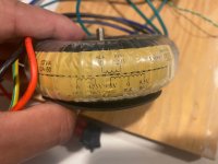
Power transformer form Audiophonics with secondary voltage 182.5 and 10.75 x 2.
Voltage measurement across capacitors in Power supply:
C4P - 252.2
C5P - 138.3
C7P - 138.5
C8P - 138.1
C1P - 14.2
Voltage on tube sockets, without tubes installed:
Pin 1 and pin 6 , pin 3 and pin 8
V1 78.8 78,8 0 0
V2 88.8 88.8 0 0
V3 138.2 138.2 9.7 9.6
Best regards.
Sasha.
As I have mentioned before the HV DC at C4P 252.2V.
Power transformer form Audiophonics with secondary voltage 182.5 and 10.75 x 2.
Voltage measurement across capacitors in Power supply:
C4P - 252.2
C5P - 138.3
C7P - 138.5
C8P - 138.1
C1P - 14.2
Voltage on tube sockets, without tubes installed:
Pin 1 and pin 6 , pin 3 and pin 8
V1 78.8 78,8 0 0
V2 88.8 88.8 0 0
V3 138.2 138.2 9.7 9.6
Best regards.
Sasha.
That's that theory out of the window then. I'd forgotten you'd posted voltages of the first power cap, and that's bang on. Afraid I'm all out of ideas, and I'd just be guessing.
Vivant is really the best man to talk to, but he's not been on for ages. Bigman may be able to help. Sorry I can't be any more help.
Vivant is really the best man to talk to, but he's not been on for ages. Bigman may be able to help. Sorry I can't be any more help.
- Home
- Source & Line
- Analogue Source
- Bigbottle Phonostage Builders thread