What transformer? If the R26-90 you have to put the LV secondaries in parallel but also make sure they are phased properly!
No not the R26-90 it is a toroidal that I had made in the UK with a 9.5-0-9.5 and 165 hv secondary which actually gives 179 volts unloaded.
If the LEDs arent lightning up, they are possibly in backwards.No not the R26-90 it is a toroidal that I had made in the UK with a 9.5-0-9.5 and 165 hv secondary which actually gives 179 volts unloaded.
Double check.
As for the Viltages, I must have missed Craig's mods for the valve change
Ye sure. I think I added £5? Just to cover the Jfet really.
Thanks!
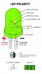
If the LEDs arent lightning up, they are possibly in backwards.
Double check.
As for the Viltages, I must have missed Craig's mods for the valve change
Just reread a bit and realise that the led's only light up in MM mode which I hadn't switched to😀
Good evening all.
Nearly finished with assembly, waiting for few more components.
Oliver, could you please confirm:
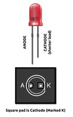
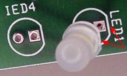
Position of LED, square pad is Anode?
Voltage supply to PCB 9,5 - 0 - 9,5 to LV and 0 - 165 to outside pins of HV?
MM or MC - switch position open or closed?
Best regards.
Sasha.
Nearly finished with assembly, waiting for few more components.
Oliver, could you please confirm:
Position of LED, square pad is Anode?
Voltage supply to PCB 9,5 - 0 - 9,5 to LV and 0 - 165 to outside pins of HV?
MM or MC - switch position open or closed?
Best regards.
Sasha.
Square pad = Cathode.
Pardon the many files. But I enjoy doing this. It teaches me to remember. I hate always having to google it...when I'm soldering. One day....
Pardon the many files. But I enjoy doing this. It teaches me to remember. I hate always having to google it...when I'm soldering. One day....
Attachments
Last edited:
Good evening all.
Nearly finished with assembly, waiting for few more components.
Oliver, could you please confirm:
Position of LED, square pad is Anode? - see diagram above.
Voltage supply to PCB 9,5 - 0 - 9,5 to LV and 0 - 165 to outside pins of HV? - Yes
MM or MC - switch position open or closed? MC - Open. Leds light up in MM
Best regards.
Sasha.

Just wanted to ask why use tubes that have different heater voltage? PCC88 is 7-7.6V (better to power them via 300mA CCS) and ECC83 are 6.3/12.6V?
Why not ECC88 so the sake of simplicity? I know it is not as cheap as PCC88 ...
Have I now mised the latest group buy ? I'm sorry, I don't visit every day, and this thread is a bit muddled between the buyers and the builders. Sorry !
Awesome, thank youi made a payment. i will follow this thread
I've seen price mentioned. But you could still use ECC88 by hacking the board. I haven't seen a schematic yet. I suppose a little IC is used to supply the 7volts...you could omit that, cut the traces and wire the socket directly to your 6.3V supply. Or perhaps even without cutting traces...Why not ECC88 so the sake of simplicity? I know it is not as cheap as PCC88 ..
The reason was gain and Millar Capacitance.Just wanted to ask why use tubes that have different heater voltage? PCC88 is 7-7.6V (better to power them via 300mA CCS) and ECC83 are 6.3/12.6V?
Why not ECC88 so the sake of simplicity? I know it is not as cheap as PCC88 ...
This valve combination gives the right amount of gain for what we wanted.
The combo also gave lower Millar Capicatnce than you would get from a phonostage with 3x ECC83
At the time, PCC88'S were plentiful and far cheaper than 83's too.
There were 3 very good reasons
Perfect! Thanks. Not sure I'm gonna do it. But at least now I know how.Bas and landiepete see craigstones solution in post 318.
What transformer? If the R26-90 you have to put the LV secondaries in parallel but also make sure they are phased properly!
Craig it's LV secondaries in series, to make 9-0-9, or put another way 18V centre tapped.
Don't worry if it's a brain fart, I've had a big one of those recently 🙄
I have connected the L/V side of things and my unloaded heater voltages across pins 4 and 5 are 6.49v. With the valves in place the heaters glow and the voltage drops below 6.3 volts. Using 6DJ8's with Craigs suggested mod.
With the H/V connected I have the following readings all measured to ground :- V1 pin 1 135.2V pin 2/3/7/8 0V pin 6 135.2V
V2 :- pin 1 149.9v pins 2/3/7/8 0v pin 6 150.2v
V3:- pin 1 236.3v pin 2 17.25v pin 3 16.69v pin 6 236.3v pin 7 17.17v pin 8 16.67v. I forgot to say the led's do not light up.
TIA
Nobody? Seems my confidence has deserted at the final hurdle😕
- Home
- Group Buys
- Bigbottle MM/MC Hybrid Valve Phonostage PCB