Maybe the boxyness is from the square shape, a surprising amount of energy hits the edges and corners. Try some MDF wings on the sides and see if that helps. I’ve had some success with 10” concrete forms (Sono Tube) cut into quarters to help remove bizzaro refractions. The concrete forms are easily cut with a saber saw and they worked better than foam blocks To address the refraction.

I was wondering if you considered positioning the woofer in an ‘Allison config‘ firing sideways along the wall with a crossover of 200hz or lower? To get it to work right you have to position the woofer as close to the floor-wall junction as is possible. That would give you more bass lift from the sealed enclosure. Also, it’s supposed to get rid of floor bounce. Downside is, you can’t put a bookshelf in between your speakers.
I'm currently doing the same, I made some full range speakers, with the intension of adding stands with subs in if they didn't have enough bass slammed against a wall, they don't so I'm currently using some previously made two ways (with a car sub choke) to fill in some bass, and for such a crude mock-up, they sound suprisingly good. So now I'm considering using the same drivers as the two ways in the "bass stands", and all drivers driven by it's own 3 watt chip amp, with active cross over.Hi @ianbo and @GM
I'm so sorry it's taken me an age to reply to your very generous and helpful messages! My life turned upside down a little in late April, with the end of a long-term relationship, and I've been off the speaker-building wagon since, but now trying to revitalise this project.
I'm going to come back to questions of build materials, bracing etc., but I'm inclined to go with 18mm ply, well braced (although slightly daunted by the complex best-in-breed brace which meets the back of the driver – we'll see about that). On driver selection, I'm having to consider availability. There only seem to be 2x Beymas in stock anywhere, and I'd quite like to build a couple of sets of these speakers if the first goes well. The Peerless and Dayton and both available on soundimports. Dayton slightly more expensive but better sensitivity match to the Pluvia, so perhaps worth it.
@ianbo I'm so grateful to you for simulating the design! Thank you so much! Would you be happy to talk it through over the phone at some point, so I can get my head around it properly? I'm surprised by the drop-off in the high mids/highs, and wondering if a 2nd-3rd order XO would help. I'm also interested in the sealed vs vented question. Ideally, I'd like to go lower than 50hz at -3db. And, with the physical volume of the deisgn being so large, I feel people will expect it to go pretty low. Which is why I'd gone for vented, which was yielding an f3 of more like 38hz. And by my calculation the Peerless has an EBP of 54.28, making it suited to sealed or vented? But I'm very new to this, so keen to be guided by those with experience!
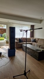
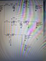
Anyhow, for now I've worked up a pair of 'prototypes' to test the WAW principle with the Pluiva and to play around with crossovers. I've just made the top part of the periscope and crossed it to my old pair of Mission 770 freedoms, which have okay low-end. Photos attached. I went for a 400hz XO (which maybe compensates for the planned distance between drivers better than a 500hz XO?), 2nd order butterworth (see screenshot).
They're sounding alright to me! Possibly a little 'boxy' in the mid range. But they're currently in a very poor sounding room, I think. My next step is to take them to a treated room in the recording studio I work at, compare them to studio monitors, and get some engineers' ears on them. If the basic concept is working well in those conditions, then I might go for a proper prototype using the bigger 12" driver and the 75L cabinet, depending on all the pending decisions above of course.
Lewis
I would second the suggested use of holy braces.
Don't worry about the drop-off in the mid/highs on my sim: a simulation based on TS parameters will always have a falling frequency response, because of the inductance in the voice coil.
Real-world full range drivers like the Pluvia don't actually have that response shape.
There's not much else I can say. I used Basta! for the sim, and I really like it for this type of rough design work, feeding in box, baffle, TS parameters and crossover. You can learn a lot from playing around with it. But you'd need a PC to take that forward yourself.
Beyond that, measurements are the only way to be sure what's going on in your design. The boxiness you mention could be many things - ears can't always tell what's going on.
a simulation based on TS parameters will always have a falling frequency response
More that they don’t tell you about anything above the mass corner of the driver.
dave
Well, in a program like Basta! you can feed in box volume, baffle size/shape, and passive or active crossover, as well as TS parameters. You can learn fair bit from that - not just the likely LF response shape.
But, of course, if you really want to know what's going on you need good measurements of the response of the driver/s in the box/baffle. And then you need to be able to use more capable software, such as Vituixcad. That's a lot of learning, though.
But, of course, if you really want to know what's going on you need good measurements of the response of the driver/s in the box/baffle. And then you need to be able to use more capable software, such as Vituixcad. That's a lot of learning, though.
Looks like the excel sheet from Julius (AudioJudgement).
As mentioned before, the only way to know what to do is measuring the speaker placed inside the cabinet.
VituixCad can be a little scary to start with but if you understand the basics it's a life changer.
As mentioned before, the only way to know what to do is measuring the speaker placed inside the cabinet.
VituixCad can be a little scary to start with but if you understand the basics it's a life changer.
Attachments
THanks again everyone.
@Arthur Jackson yes I guess it could be a diffraction thing. Thanks for the tips. After listening a bit more and with a different amp, I'm not sure how much of a problem there is, but will keep it in mind when I come to testing (and maybe measuring) properly. I don't think the Allison config is going to work for me as it's important that these speakers aren't too fussy WRT placement or surrounding furniture.
@ianbo Thanks for clarifying. I don't want to push my luck, but I'd be really curious to see a simulation of the design I've had in mind – vented, and with the 2nd order crossover I screen-shotted above. I don't know how long that would take in Basta... if it's super easy, is there any chance you might be able to help?!
After a fair bit of listening at normal levels, I ended up playing my crude prototype speakers at very high volume for a few hours recently, when hosting a party. Probably not wise! But I'm glad I did it because the crossovers ended up overheating, indicating a serious design flaw. The main culprits, which burnt through the cable ties fixing them to the crossover board (!!), were the 15ohm resistor (final component before tweeter) and the 4.7mH inductor (first component on the woofer side of the XO). Other components felt quite hot, but not causing any plastic to melt...
My research so far has revealed a few potential issues which could cause overheating in a passive XO:
Anyone have any ideas on this?
My research so far has revealed a few potential issues which could cause overheating in a passive XO:
- Wrongly rated resistors. I think this was an issue for me, as I'd stupidly bought cheapo 10W resistors. Easy to replace with better, higher-rated resistors in the final design.
- Wire gauge on inductor coils. This could well be an issue. The problematic 4.7mH inductors seem to have a ⌀ of '0.5'. Not sure what that refers to, but perhaps wire gauge? Does anyone have any guidance around appropriate gauge, and whether this is likely to have caused problems in my case?
- Bad design in terms of inappropriate driver choice or crossover frequency. It'd be really interesting to hear if this could be a problem in my case. I don't know any reason why it would be (why would it be problematic to HP filter a full-range driver at 400hz? or likewise to LP filter a mid-woofer at the same frequency?). But of course I'm a novice, so it's very possible there's something I'm missing!
Anyone have any ideas on this?
Probably need thicker wire for the inductor on the woofer. Look for an iron core, they are fairly cheap and have low resistance.
The resistor couldn't handle the watts you were putting through. If you have a 15Ohm rated at 10watts you can double the value and make it a 20 watts.
So 30Ohm x 10 watts (parallel)= 15Ohm 20 watts.
The resistor couldn't handle the watts you were putting through. If you have a 15Ohm rated at 10watts you can double the value and make it a 20 watts.
So 30Ohm x 10 watts (parallel)= 15Ohm 20 watts.
The crossover you were using was for the Mission and Pluvia combo? I can't sim that, as I don't know the TS parameters of the Mission woofer. If you really want to understand what you're doing, I'd suggest you should give Basta a go yourself. It's a free download from the Tolvan data website. (Or try other software, xsim for example.)
The 0.5 marking on the inductor that burnt out almost certainly means 0.5mm diameter wire. That's a very light gauge for a series woofer inductor. I don't understand where the resistor was in your circuit - it's not shown in the diagram.
If I was you I'd read up more on speaker design before going any further. You're lucky it was just a few components that went up in smoke.
Thank you @ianbo and @Wootoo !
The resistor was the final component in the circuit on the tweeter side. It's not in the diagram but I added it into the circuit to compensate for differences in sensitivity, balancing the output volumes of the two drivers.
I did mean this crossover, but with the Peerless or Dayton 12" woofers I had suggested, not the Mission driver (I used that temporarily to test the principle of the WAW design and try building a crossover before committing to v expensive cabinet builds). However, I appreciate I was pushing my luck – don't worry if it's too much effort. Unfortunately Basta!, like all the the other sim software, seems to be PC-only. I only have access to a mac, which is becoming a real pain! I'd love to be able to do some simulating.The crossover you were using was for the Mission and Pluvia combo? I can't sim that, as I don't know the TS parameters of the Mission woofer.
Thank you! And likewise @Wootoo for similar comments. Besides looking for an iron core inductor, do you have any guidance regarding the appropriate gauge?The 0.5 marking on the inductor that burnt out almost certainly means 0.5mm diameter wire. That's a very light gauge for a series woofer inductor.
The resistor was the final component in the circuit on the tweeter side. It's not in the diagram but I added it into the circuit to compensate for differences in sensitivity, balancing the output volumes of the two drivers.
I'm doing my best! But good to be reminded to proceed with caution. Sometimes it feels difficult to find the info without asking the forum tbh – I did do some research before my last post, for example, but there wasn't much about inductor wire gauge out there.f I was you I'd read up more on speaker design before going any further. You're lucky it was just a few components that went up in smoke.
And just to say, I did attempt to use Vituix or Xsim (can't remember which one now) on my Mac using Wine, the programme which is meant to give mac users access to PC software. But there was a compatibility issue with more recent Mac OSs, making Wine unusable. I haven't found any way to access those programmes on mac as yet! Besides buying a new computer...Unfortunately Basta!, like all the the other sim software, seems to be PC-only. I only have access to a mac, which is becoming a real pain! I'd love to be able to do some simulating.
@lewisb I'm sorry if my previous post was a bit harsh. But burnt out crossover parts are actually quite unusual, and are a real safety concern.
I'm troubled that the resistor you added in series with the pluvia was a 15 ohm - that's very high! A 15 ohm resistor in front of an 8 ohm driver will be dissipating most of the power you send it, and cutting the sensitivity of the driver hugely. Playing a speaker like that at party levels is not a good idea. (10 W is usually ok for resistors on mid/treble crossovers - its the 15 ohm resistance that bothers me.)
I'm puzzled as to why you needed such a big resistor to get the balance right. It makes me wonder if the 4.7mH coil on the woofer was an air core part? If so, it would have a very high dcr, (maybe in the region of 4 ohms?) which would again mean it was dissipating a lot of power, and cutting the sensitivity of woofer significantly. I'm guessing, though.
A woofer inductor should usually have low dcr - well under 1 ohm. Hence cored inductors tend to be chosen. Apart from the issue of damping, low dcr means low power dissipation, and much less danger of overheating. Go for whatever wire gauge gives you something like 0.3 ohms dcr. (1mm would be a reasonable starting point, probably.)
But burnt out crossover parts are actually quite unusual, and are a real safety concern.
Since what goes is a too small a resistor. We lit the foam lining of a set of Tangent RS4s on fire by overheating such with a Bryston 4B. Created a VERY stinky white acrif smoke streaming out the square vent (blew up amidbass as well).
dave
Hi again,
This is all starting to add up. The resistor wasn't fit for purpose, both because it was a cheap 10W one (more sensitive to burning out) and because it was dissipating too much power. I was using such a strong resistor unnecessarily, probably in part because the prototype speaker was using a different woofer to the driver I'll eventually be using, and likely a less sensitive woofer. So the 15ohm resistor was compensating for that, I imagine. It was also generating quite a low-end-heavy sound (which I don't mind), so was probably higher rated than needed.
Making matters worse – thanks @ianbo for flagging this – the inductor which got burnt out (one of these, 3808: https://impactaudio.co.uk/products/visaton-kn-ferrite-core-coils?variant=15302709805123) also wasn't fit for purpose. Not only because of the thin wire gauge, but because of its dcr of 2ohm.
So my takeaways are:
I feel like the burnt crossover makes sense now, and I know how to avoid the same happening again. So I'm tempted to build these speakers up. Unfortunately I haven't been able to do any proper simulation but I'm not sure there's an easy way around that! It can't sound that badd... can it?
Lewis
This is all starting to add up. The resistor wasn't fit for purpose, both because it was a cheap 10W one (more sensitive to burning out) and because it was dissipating too much power. I was using such a strong resistor unnecessarily, probably in part because the prototype speaker was using a different woofer to the driver I'll eventually be using, and likely a less sensitive woofer. So the 15ohm resistor was compensating for that, I imagine. It was also generating quite a low-end-heavy sound (which I don't mind), so was probably higher rated than needed.
Making matters worse – thanks @ianbo for flagging this – the inductor which got burnt out (one of these, 3808: https://impactaudio.co.uk/products/visaton-kn-ferrite-core-coils?variant=15302709805123) also wasn't fit for purpose. Not only because of the thin wire gauge, but because of its dcr of 2ohm.
So my takeaways are:
- Try to get a higher sensitivity woofer if possible, so ideally i won't need a resistor on the wideband driver at all
- Use higher quality crossover components with appropriate wattage and wire guages
- In particular, make sure my inductors are low dcr so they're not adding unwanted resistance to the circuit
I feel like the burnt crossover makes sense now, and I know how to avoid the same happening again. So I'm tempted to build these speakers up. Unfortunately I haven't been able to do any proper simulation but I'm not sure there's an easy way around that! It can't sound that badd... can it?
Lewis
@Wootoo that would be incredibly generous, and greatly appreciated! Thank you so much for offering.
The full-range I'm planning to use is the Markaudio Pluvia 7.2HD: https://www.markaudio.com/online_shop/pluvia/pluvia-7-2-hd/
The woofer I was planning to use is the Peerless SLS-P830669: https://www.soundimports.eu/en/peer...ausEutMfHYIZAyHifzH0QR70nTqC0a4saAuySEALw_wcB
However, the Peerless is only 4.1dB more sensitive than the Pluvia. Having considered the shortcomings of putting a big resistor in front of the Pluvia to balance the sensitivities, I have been wondering if it might be more sensible to use a more sensitive woofer. The best candidate in my price range, as far as I can tell, is the Dayton Audio DS315-8, which is 5.3dB more sensitvie than the PLuvia: https://www.soundimports.eu/en/dayt...qQuaccXpkoKAFcK41zc_r0s2BXHfTCARoCfO4QAvD_BwE
I don't know if you have a view on which woofer is the best idea. But if in doubt I think I'd like to model with the Peerless and go from there.
If you can't get the frd or zma files, I learnt to trace them so should be able to do that for you if helpful!
Thanks again
I would definitely go for the peerless since it's closer to the Pluvia in sensitivity.
Hopefully I can take a look at it for you this weekend.
Hopefully I can take a look at it for you this weekend.
- Home
- Loudspeakers
- Full Range
- Big, strange WAW project