Hi Srinath
BE CAREFUL AS THE PS IS +/- 80 VOLTS AND THIS CAN KILL.
Since your are not a TECH I suggest that you get a real tech to help you.
You could try this. When removing the connector tape it so it will not short when running the tests.
The BGW 750x has 2 modules that plug in. They are identical. On the amp that trips the circuit breaker(Mag switch) disconnect one module and turn on the power if it trips, the module is BAD. Disconnect the BAD module and connect the other and turn on the power, if it stays on that module is GOOD. Get someone to repair the bad module as it has SHORTED OUTPUT TRANSISTORS and some other bad parts.
The BGW 250x is similar to the 750x
Duke
Duke you beat me to the punch 🙂
Srinath, you should easily be able to get one amp working. Remove the top cover of the amp that trips the breaker. Make sure the amp has sat idle for a long time and the power supply capacitors have fully discharged. Remove one amp module and disconnect the octal umbilical plug. Insulate the male octal plug well with electrical tape.
Plug the amp back in and see if the breaker trips. If it doesnt, you have identified the problem channel. You can then take the working module from your second amp and replace the faulty module from the first amp. Those octal plugs are keyed so they can only go in one position and the amp modules can be swapped left to right, amp to amp.
As Duke had already mentioned, a tripping breaker on these amps usually points to shorted output transistors but there is a slight possibility of a power supply issue if the breaker continues to trip without any modules plugged in.
I forgot to tell you about the THERMAL SWITCHES on the 750x modules. They control the fan and they are part of the AC POWER LINE. INSULATE THEM DURING TESTING.
Duke
Duke
I can do that myself
OK I can do that type of thing myself.
I have disconnected and removed these and played with it a bit already.
I know to replace power transistors, driver transistors and the emitter resistor as well as test and replace other stuff.
I've so far not seen anything in this amp I don't think I can tackle but, the entire thing I don't want to rebuild, the burnt one has a few burnt traces etc etc. That I don't want to try to fix, mainly cos I'd spend more than you can buy a nice looking one for and this one looks awful.
I'll start on it and post back.
Thanks.
Srinath.
Hi Srinath
BE CAREFUL AS THE PS IS +/- 80 VOLTS AND THIS CAN KILL.
Since your are not a TECH I suggest that you get a real tech to help you.
You could try this. When removing the connector tape it so it will not short when running the tests.
The BGW 750x has 2 modules that plug in. They are identical. On the amp that trips the circuit breaker(Mag switch) disconnect one module and turn on the power if it trips, the module is BAD. Disconnect the BAD module and connect the other and turn on the power, if it stays on that module is GOOD. Get someone to repair the bad module as it has SHORTED OUTPUT TRANSISTORS and some other bad parts.
The BGW 250x is similar to the 750x
Duke
OK I can do that type of thing myself.
I have disconnected and removed these and played with it a bit already.
I know to replace power transistors, driver transistors and the emitter resistor as well as test and replace other stuff.
I've so far not seen anything in this amp I don't think I can tackle but, the entire thing I don't want to rebuild, the burnt one has a few burnt traces etc etc. That I don't want to try to fix, mainly cos I'd spend more than you can buy a nice looking one for and this one looks awful.
I'll start on it and post back.
Thanks.
Srinath.
Well... just to keep an old thread going! 🙂
Yes! I am a little slow to the party, and yes I am a beginner, so have read the thread twice already.
I picked up a 750C a while ago, plugged my ipod in via phono just as a quick test, both channels played, after about a second I heard a little click and the right channel went off.
After being unplugged for a while I took the top off, removed cleaned and re-bent the phono connectors as they were somewhat well used loose and dirty.
Really dusty and rather dirty inside, don't think its has been cleaned out for years upon years!!
Plugged it back in and same thing happened. Click and right side went off.
Oh yes the fan comes on as soon as the amp is switched on, and yes it is rather noisy.
So after all the reading, I don't seem to have come across anything about a safety or overload trip out for an individual module, is there such a thing?
Sound wise, using some old mission bookshelf's I would say it was rather an unusual sound, plenty of power in reserve which is lovely, treble is quite smooth and spaced out, bass is there with power but maybe a little spaced out too, I did enjoy listening to just the left channel for a good while which I was quite surprised about as usually listening to just one channel I find rather lacking in comparison to stereo.
So I think it will be an interesting learning project, as long as I am not too far behind the times and am still able to get suitable parts!
I don't quite get the transformer bit with the round shorting plugs, but guess getting the thing working will be the first step.
(No caps or plugs are present with this unit, I do have a XO that outputs balanced so at some point it would be interesting to try balanced, so long as I get it working!)
Cheers
DC
Thats a mystery. The 750B and C`s have DPDT relays inline with the speaker outputs. Should a fault occur in one channel, the relay would trip and disconnect both outputs simultaneously.
Has the amp been modified?
Has the amp been modified?
Hi DC,
Well, there is a DC protection circuit, and of course there is that bipolar 80 VDC supply. I wouldn't recommend this as a learner amplifier! It has a lot of power, and it can sound really good if you know what you're doing when you repair it. It's old enough so that it may have been "hacked" already. In this instance, the work "hacked" means very bad things. BTW, both channels should have disappeared. It is possible that the relay contacts may be welded together on one channel. Pull the relay and inspect the contacts.
Can you take high resolution pictures of each board under the heat sinks?
Leave the circular shorting plugs alone. They are perfectly normal. There are transformers that can plug in there as an option. You don't need them. Besides, they are PA quality, so you are further ahead the way you are. So much for balanced inputs.
All a balanced input and output are is adapters. Everything internally is single ended. So at best, a balanced signal can be just as good as the single ended if everything is perfect. There are times when you have to run a signal a long way. That is when you might use a balanced signal.
-Chris
The bad side doesn’t trip the relay immediately so it may just be a dried out capacitor from 30-40 years ago.
But unless it has two relays, how is it clicking itself off?
Thermal switches, do they click?
I would start checking for dc offset on the speaker terminals and see what that is...
But unless it has two relays, how is it clicking itself off?
Thermal switches, do they click?
I would start checking for dc offset on the speaker terminals and see what that is...
Does this amp use circular plugs to connect the channels to the power supply/housekeeping circuitry? Try removing and reinstalling the plugs if it does.
Craig
Craig
Last edited:
Yes, it is a BGW-750C and does use the octal plugs to connect to the boards from the chassis.
The timing circuit is working, hence the "click" a few seconds after turn-on. I think the contacts are melted together on one channel and just burned on the other.
DC, you can work on these while you apply power, BUT the board can short against the chassis very easily when you do that. This is really a repair for someone experienced. It's a big amp and there is a lot of energy just waiting to go somewhere you don't want it to.
-Chris
I started to call them octal plugs but with 11 pins it's not octal, not even going to guess what the 11 pin equivalent is. If the relay is bad it should be an easy fix, well worth the effort.
Craig
Craig
The CLICK is the DC Protection relay. The LEFT channel contacts are welded together and the RIGHT channel module is defective. The rear panel silver capped connector plugs are needed to remain in for unbalanced mode operation. If Balance mode in needed the isolation transformers plug in or filter can be plupged into the sockets.
Duke.
Duke.
Last edited:
Wow so many replies Thank You!!
Michael F
Modified... Arr funny you should ask that, I bought the amp from a recording studio, and hence thought it must be of reasonable quality and should have been looked after due to its professional every day usage...
It was advertised with non original bgw transformers, and that the front volume pots were bypassed due to the fact they were not balanced and in the signal path. It was modified by the in house technical department.
So I guess, this makes things more interesting.. or difficult! If other things have been modified/tampered with!
Chris
Yes hacked! If I am a beginner and things have been hacked it could make things rather iffy for me! Yep I was rather careful once I had actually seen how huge the smoothing caps were, and will quite happily leave it for a good number of days unplugged before having a better look inside! I did have a big resistor with croc clips to discharge 4700uF caps but they are obviously teeny weeny in comparison! I shall have to check the spec of the resistor.
80Vdc is rather a lot!
I shall disassemble and check the relays 🙂
Yes I shall take pics of the boards, by all means.
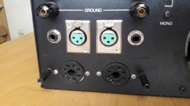
..and a pic of the balanced sockets on the back, so it is clear what is there, may be not to me but to those who know how they work.
Interesting to know that the balanced part stops as it goes in to the amp and the amp is single ended. Which I guess makes sense as it is the long cable runs that Pro set ups use the balancing for over the long distance cable runs, to keep the signal in check.
Phase
Dried out cap could be simple 🙂
I shall have a closer look at the board soon, check out the caps,
I would guess thermal switches do click in amps?, they do in electric showers...
I shall have a ago at measuring DC offset.
Craig
Yes it does have round plugs one to each board, I shall unplug and re-plug, yes could be dirty, oxidised etc, as I guess from the state of the inside of the amp it has never been cleaned out!!
Chris
Thanks for the tip about working with power applied, and how much power there is in the amp, I think at the moment I shall only be working/checking the insides out, once it has been off for a good while as I don't fancy anything shorting, especially to in experienced me! 🙂
Craig
octal, 8? may have been 8 wires to the round plug? I shall have a count next time 11 seems a lot for what I remember, we shall see, anyways will unplug and re-plug the round bits 🙂
Duke
DC protection, uh oh, left welded and right module defective, maybe the amp was not as well maintained as I had hoped...
There don't seem to be any connector plugs in the rear, just 6 or 8 holes in two circles for something to plug into, still the phono in's don't relate to those silver capped plugs do they? (phono is what I shall use for the time being)
Okay so
disassemble, check out boards, photos, look at relays, caps etc,
unplug and re-plug board round connectors plugs
check dc offset
report back 🙂
Wonderful! Cheers
hope to do above before Sunday 🙂
Michael F
Modified... Arr funny you should ask that, I bought the amp from a recording studio, and hence thought it must be of reasonable quality and should have been looked after due to its professional every day usage...
It was advertised with non original bgw transformers, and that the front volume pots were bypassed due to the fact they were not balanced and in the signal path. It was modified by the in house technical department.
So I guess, this makes things more interesting.. or difficult! If other things have been modified/tampered with!
Chris
Yes hacked! If I am a beginner and things have been hacked it could make things rather iffy for me! Yep I was rather careful once I had actually seen how huge the smoothing caps were, and will quite happily leave it for a good number of days unplugged before having a better look inside! I did have a big resistor with croc clips to discharge 4700uF caps but they are obviously teeny weeny in comparison! I shall have to check the spec of the resistor.
80Vdc is rather a lot!
I shall disassemble and check the relays 🙂
Yes I shall take pics of the boards, by all means.
..and a pic of the balanced sockets on the back, so it is clear what is there, may be not to me but to those who know how they work.
Interesting to know that the balanced part stops as it goes in to the amp and the amp is single ended. Which I guess makes sense as it is the long cable runs that Pro set ups use the balancing for over the long distance cable runs, to keep the signal in check.
Phase
Dried out cap could be simple 🙂
I shall have a closer look at the board soon, check out the caps,
I would guess thermal switches do click in amps?, they do in electric showers...
I shall have a ago at measuring DC offset.
Craig
Yes it does have round plugs one to each board, I shall unplug and re-plug, yes could be dirty, oxidised etc, as I guess from the state of the inside of the amp it has never been cleaned out!!
Chris
Thanks for the tip about working with power applied, and how much power there is in the amp, I think at the moment I shall only be working/checking the insides out, once it has been off for a good while as I don't fancy anything shorting, especially to in experienced me! 🙂
Craig
octal, 8? may have been 8 wires to the round plug? I shall have a count next time 11 seems a lot for what I remember, we shall see, anyways will unplug and re-plug the round bits 🙂
Duke
DC protection, uh oh, left welded and right module defective, maybe the amp was not as well maintained as I had hoped...
There don't seem to be any connector plugs in the rear, just 6 or 8 holes in two circles for something to plug into, still the phono in's don't relate to those silver capped plugs do they? (phono is what I shall use for the time being)
Okay so
disassemble, check out boards, photos, look at relays, caps etc,
unplug and re-plug board round connectors plugs
check dc offset
report back 🙂
Wonderful! Cheers
hope to do above before Sunday 🙂
Just for your info Audio1Man, Duke, was an engineer at BGW so you are in good hands here. BGWs are good solid performers once up to spec, well worth the effort.
Craig
Craig
Hi DC,
There is one relay that is held in the socket with a spring wire that goes over the top. If you can maneuver it to one side, the relay just unplugs. New relays exactly like the old one there are available. I know I have bought them from Digikey before.
I still see them come in, and I normally strip them down and rebuild them. Once done they perform quite well. Noisy fans should be replaced. Don't even bother to try to clean it. The bearings are shot by now.
If you elect to work on this one, use a digital camera and take many pictures of how everything is put together. Take pictures that show the transistors in the heat sink, as well as on the PCB on the back. When you remove all those transistors the PCB will come away from the heat sink. Clean all the old grease off and give the heat sinks a good wash. To rebuild this into a really nice amplifier, just buy a set of new outputs for it. I've used MJ21195 and MJ21196 with great success. The other thing about these is that they match a lot closer in gain, so getting a matched set of outputs to use is a lot easier and cheaper. Use new Mica insulators for all power transistors and fresh heat sink grease. I still use Wakefield 120. They sell it in tubes, I buy tubs of the stuff. A #2 artist's brush is about the best thing I have found for applying an even coat of grease. It shouldn't be a thick coating, and you just snug it down, don't really tighten the screws down. On-Semi has a very good app note on mounting power transistors.
One reason I change all the outputs is that they normally have had a couple changed. That isn't a good repair. Also, the matches between transistors is much better today than it was when these were manufactured. Matching the output transistors can reduce distortion by 20 dB before feedback. You can measure the lower distortion, that's how big a change this can make. On-Semi did the tests and documented this distortion reduction and I have confirmed it in my own lab. Do not try to change the LM318 op amp. It is very fast and the amplifier is designed with it. If you replace the op amp, you will have to compensate the amplifier, and you are not prepared to do this. A really good technician probably could, just don't.
If you take your time with this, you will end up with a very, very nice amplifier. They are super reliable too.
-Chris
Don't forget the BLOWOUT MAGNETIC that are glued to both sides of the relay case near the contacts.
Duke
Duke
Hi Duke,
Yes, I thought that was a brilliant addition. I swap the outer covers when changing relays.
-Chris
Yes, I thought that was a brilliant addition. I swap the outer covers when changing relays.
-Chris
Hey Thanks for all the pointers, appreciated 🙂
The writing becomes clear once one ties it to the actual physical equipment.
Regarding the power transistors, they all look the same, well half of one type and half of another, I shall attach some pics shortly.
I found the relay, and had to undo the 4 retaining screws underneath its cct board to get the nuts off that hold the wire springy thing over the top of its' plastic case. I did try to be very careful in removing the plastic case (with the magnets glued on the side) - (I have now read up as to what they are for! Interesting!) But I did crack it slightly so I am pleased the wire over the top of the case is there to ensure it stays in place.
The relay seems to physically work fine when i squeeze the actuator, two little flaps with contactors on the end of them move between two front contacts and then two back contacts when moving the actuator. Nothing seems stuck, it actually looks reasonably clean and new compared to the rest of the stuff in the case. (Writing this, I am now thinking, I did not electrically test it! May be I should have done just to be sure!)
I assembled the amp and tested for DC offset. Left side registered around 7 (pic soon) and right started lower and very quickly diminished to Zero. I initially thought zero was good as we don't want dc, but after plugging in the speakers I am guessing that zero is not good, as there is no sound from the right, just like before.
So any suggestions or thoughts, with this update, please 🙂
- Home
- Amplifiers
- Solid State
- BGW 750B output modules