Trying again to attach ;-)
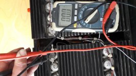
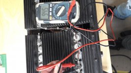
Thermostat resistance readings when cold and off.
Thermostat resistance readings when cold and off.
Attachments


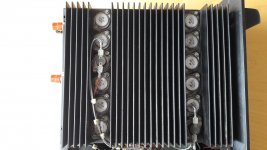
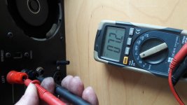
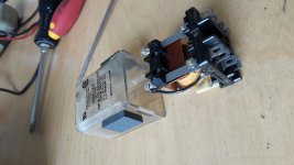
There are two thermal switches per channel, one directly connected to the output of the amplifier, too much load and it goes open until cooled. The other is for the fan, too hot and the fan speed goes up. The load switches should have zero Ohms when cold and the fan switches should be open and should read 300 Ohms or so.
Craig
Craig
Last edited:
I would try and swap the module to see if the problem stays with the modules or stays with the chassis. If the FAN WIRING is to short remove and tape the wires for the test.
Duke
Duke
There are two thermal switches per channel, one directly connected to the output of the amplifier, too much load and it goes open until cooled. The other is for the fan, too hot and the fan speed goes up. The load switches should have zero Ohms when cold and the fan switches should be open and should read 300 Ohms or so.
Craig
Okay, so the switches near to the edge of the heat sink on both modules is wired to the underside of the cct board on each individual module, might I guess these are the output connected ones, as they are closed/zero ohms?
The other two switches, more to the middle of the rows of transistors, have much longer wires and go into the loom somewhere, I might guess these are the fan ones and should be open but as they have some resistance the fan comes on pretty much straight after the amp is switched on...
Cheers for the info!
The fan normally runs at low speed thru the 300 Ohm resistors and that's what you're reading across the open switches. When one or both of the modules get too hot the switch(s) will close bypassing the 300 Ohm resistors and the fan will be on high speed until the module cools down.
Craig
Craig
I would try and swap the module to see if the problem stays with the modules or stays with the chassis. If the FAN WIRING is to short remove and tape the wires for the test.
Duke
Just swapped the modules the dc offset of zero stayed on the right outputs and the left outputs are now 5.5 rather than the 7 (7 when the modules were in the original location) I guess hope 😀 these measurements are enough, to conclude both modules are Working 😀 ...Or should I plug the speakers in just to confirm...
The fan normally runs at low speed thru the 300 Ohm resistors and that's what you're reading across the open switches. When one or both of the modules get too hot the switch(s) will close bypassing the 300 Ohm resistors and the fan will be on high speed until the module cools down.
Craig
Cool, thanks for explaining!
So they sound as if they are working correctly 🙂
So...
Please 🙂
... any thoughts on what could be causing the fault within the chassis wiring?
(if it is this)
To my limited knowledge, I am thinking:
- I should check the relay is conducting both left and right channels,
- check the power supply to each of the modules..
Anything else that could supply sound for a short while and then cut out?
Thanking you in advance!
🙂
Hi Deaf Cat,
There is nothing active in the chassis that can affect the modules except a defective relay where the coil voltage could get put on a speaker output.
Have you confirmed that the supply voltages are the same but opposite polarities?
Given the age of the amplifier it could have weird problems in each channel, but I doubt it. You can run the amplifier with only one module installed. How about testing one, then sticking the other in the same place and trying it again? Also measure the unconnected speaker output to see if there is any voltage on it. There shouldn't be any at all.
-Chris
Hiya,
Just thinking of other things that may affect the output..
What if the stereo/mono switch was dirty or iffy?
What if something has gone wrong with the volume controls on the front?
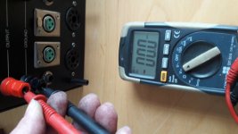
I shall have a measure of the voltages on the 11 pins (left and right, round plugs that go to each module) and report back.
Cheers
DC
Just thinking of other things that may affect the output..
What if the stereo/mono switch was dirty or iffy?
What if something has gone wrong with the volume controls on the front?
I shall have a measure of the voltages on the 11 pins (left and right, round plugs that go to each module) and report back.
Cheers
DC
Well its been a while!
I have not exactly progressed much as of yet! Time for another look though 🙂
If I swap the modules its still the rhs speaker that does not work.
I Just pulled out the relay, and this time actually measured resistance, rather than just looking! gently pushing the actuator, the one actuator does two switches, one side switches on and off, ie. Open circuit and then closed, zero resistance. The other side just stays open circuit, even though it looks like it is closed, I used some very find wet and dry paper (dry) and gently cleaned the non conducting contacts. They now show open circuit when open and closed circuit (zero resistance) when closed.
Simple fix I thought!
Ahrrrr... this time when I powered up, the clip light for the RHS lit brightly, no music even playing yet! I then played a track, no sound from the right as normal, after a while the RHS clip light gently faded out, still no sound from the right hand speaker.
After a while I switched the 750 off and then on again, the clip light did not come on next time the 750 was switched on, still no sound on the right.
I guess the next step would be to see what has happened to the relay, if it still functions correctly after the bright clip light with nothing playing!?
And go from there?
Any comments / thoughts much appreciated 🙂
Cheers
DC
Hi Deaf Cat,
There is nothing active in the chassis that can affect the modules except a defective relay where the coil voltage could get put on a speaker output.
Have you confirmed that the supply voltages are the same but opposite polarities?
Given the age of the amplifier it could have weird problems in each channel, but I doubt it. You can run the amplifier with only one module installed. How about testing one, then sticking the other in the same place and trying it again? Also measure the unconnected speaker output to see if there is any voltage on it. There shouldn't be any at all.
-Chris
Have you tried what Chris suggested?
Hi Deaf Cat,
You destroyed the relay the second you sanded it. The contacts are just a coating flashed onto the base material. So, you need a new relay. After installing that, you can test it and see if you need to do any more trouble shooting.
-Chris
You destroyed the relay the second you sanded it. The contacts are just a coating flashed onto the base material. So, you need a new relay. After installing that, you can test it and see if you need to do any more trouble shooting.
-Chris
@ anatech
I am told that you are familiar with Bryston amps.
I have a 4B that works very well after I redo the power supply
but I also have a 3B that is down on both channels.
the last time I looked at it, I found myself confronted
has references of transistors that I do not know (manufacturer's mark)
Do you have the equivalences of transistors that populate PCBs?
it's a first generation of 3B
Have you tried what Chris suggested?
Ah not quite yet..
When I read:
"Have you confirmed that the supply voltages are the same but opposite polarities?"
My brain goes 😕 in a box of electric bits and bobs where would one find the right place to measure the above mentioned voltages 😕
However! I have just found a circuit diagram! 😀 That, I should be able to follow and find the right bits to measure and I shall then report back 😎
- Home
- Amplifiers
- Solid State
- BGW 750B output modules