Hi Duke,
Thanks for taking a moment to join the discussion. It's great that we get a chance to hear from you. More importantly, thanks for the designs that have stood the test of time. I'm very impressed with the design and build of the BGW I have.
While I have not considered replacing the output transistors, I wonder if you would share your thoughts on the need and opportunity to substantially improve the sound of these amps with currently available alternatives.
Thanks!
Do you have the knowledge to change the frequency compensation?
If not, use the original type transistors.
If not, use the original type transistors.
New member with 4 BGW's. My 750B has started crackling & hissing from the left channel after being on for a short while and after 32+ years of solid service it's time to redo all that can be done to get the best audio quality and another 32+ years of use out of it. Any suggestions on caps and other mods that'll make it shine again?
I recapped the 750B and it's working great. I'm using it on the low end of a pair of EV Sentry III's.
Hi Trev,
Don't change the op amp yet. There is a procedure for balancing the driver currents as you monitor the DC offset of the 318. I'll bet you have not done that. If I only still had my manuals!!!!
On the board near the MJE devices you will see resistors with pads (or resistors) beside them. One adjusts bias current, the other two set the currents in the drivers. The spare resistor pads the value of the main one. Start by removing the pad and see if the offset gets worse, or better. Now you know which way to go. Make sure you aren't playing with the bias current! Adjust until the offset on pin 6 is below 100mV (as I recall).
I have never seen the op amp bad on these. I have seen an op amp supply capacitor short and create offset that way.
-Chris
Edit: Mark, I try to avoid NTE / ECG garbage unless there is no other way. That stuff is expensive trash.
Hi Chris,
Thanks for the very important info..
Is there any specific procedure how to do proper biasing??
Thanks and Regards,
"Is there any specific procedure how to do proper biasing?? "
340mV on the base of the outputs (class AB+B).
340mV on the base of the outputs (class AB+B).
340mV on the base of the outputs (class AB+B).
A method how to achive 340mV on the base of the output would he great..
Thanks..
You replace the value of a fixed resistor. Do you have the service manual? The resistor is in the bias transistor circuit. Often times all you do is remove any parallel resistor and hopefully by adding various values of resistance you can get to the value you want. Once you find the correct value, you just solder it in.
DC offset is set in the same way, but you monitor the DC offset of the Op Amp (LM318, pin 6). They give you a safe probing location so you're not trying this right on the chip pins. I gave you the reference so you could trace out the location.
-Chris
DC offset is set in the same way, but you monitor the DC offset of the Op Amp (LM318, pin 6). They give you a safe probing location so you're not trying this right on the chip pins. I gave you the reference so you could trace out the location.
-Chris
You replace the value of a fixed resistor. Do you have the service manual? The resistor is in the bias transistor circuit. Often times all you do is remove any parallel resistor and hopefully by adding various values of resistance you can get to the value you want. Once you find the correct value, you just solder it in.
DC offset is set in the same way, but you monitor the DC offset of the Op Amp (LM318, pin 6). They give you a safe probing location so you're not trying this right on the chip pins. I gave you the reference so you could trace out the location.
-Chris
Hi Chris,
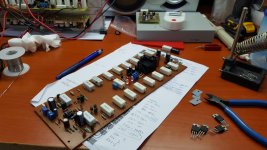
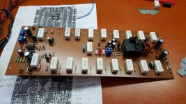
Thanks a lot for the quick response, I made this amp in my own design base on the orig. schematic on the service manual (attached pic.).
The amp. is singing with the light bulb tricks installed but when I plug direct it blows out the output.
I understand the I need to get the proper biasing on this to stabilize the amp. Since the manual did not show the closer resistor value (for R22 & R24) as a starting point then it's a bit tricky to guess.
Hope someone can give a hints the closer resistor value, TIA..
Regards,
Attachments
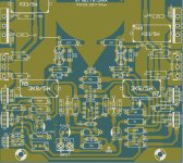
Hi I admire your project, however it needs to have HOMETAXIAL output devices in the output stages to work as designed. The output parts were TO3 2N3773 / 2N6609. I think that you used newer parts and the Ft are not below 3-4 mHz. Today's devices are 20 mHz and the layout and compensation must be part of your new design.
The AMPLIFIER is unstable and high freq oscillation is destroying the parts when high power is applied.
The adjustments for DC OFFSET or LM318 for +/- 100mv, no signal
Look @ VAS emitter resistors 100 ohm and 110 ohm. The 110 ohm is fugged with 1-3k for the adjustment
The BIAS of 340mv is the Vbe stage and I don't remember this resistor range. It should be 500 ohm range?
Duke🙂
Last edited:
Hi I admire your project, however it needs to have HOMETAXIAL output devices in the output stages to work as designed. The output parts were TO3 2N3773 / 2N6609. I think that you used newer parts and the Ft are not below 3-4 mHz. Today's devices are 20 mHz and the layout and compensation must be part of your new design.
The AMPLIFIER is unstable and high freq oscillation is destroying the parts when high power is applied.
The adjustments for DC OFFSET or LM318 for +/- 100mv, no signal
Look @ VAS emitter resistors 100 ohm and 110 ohm. The 110 ohm is fugged with 1-3k for the adjustment
The BIAS of 340mv is the Vbe stage and I don't remember this resistor range. It should be 500 ohm range?
Duke🙂
Hi Duke,
Many thanks for a very useful and important info.
I got now the exact resistor value to make it almost +/- 36mV on pin #6 of LM318 (0V was the target as per manual).
Problem solve!😉😉 and the amp. is now singing nicely and Happy..
Regards,
wiljj78, that looks like a nice project, worthy of its own thread. Now let us see the power supply 🙂
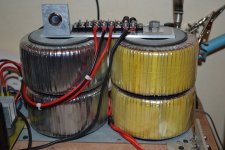

Hi wiljj78
Your mounting of the toroid's may lead to a problem. The INSULATION under the hex nut could fail if it is Teflon. Teflon cold flows and gets thinner with time as it loaded. This will make a SHORTED TURN and blow the primary fuse. Make sure that will not happen, use a thick fiber washer.
Duke🙂
Your mounting of the toroid's may lead to a problem. The INSULATION under the hex nut could fail if it is Teflon. Teflon cold flows and gets thinner with time as it loaded. This will make a SHORTED TURN and blow the primary fuse. Make sure that will not happen, use a thick fiber washer.
Duke🙂
Hi wiljj78,
Excellent news!
The value for bias should have been close to the original. There were 5 TO-126 transistors that are supposed to mount onto the heat sink. Make sure the replacements are also thermally connected. Since this is an entirely new design (new PCB design and different part numbers), you're going to have to check for stability very carefully. Make sure your zobel resistor isn't getting warm at all.
Powering stuff up.
You really need a variac to enable you to apply AC power slowly while watching the current. That should prevent you from losing more parts when you apply juice for the first time. The "light bulb" thing is a poor substitute and has characteristics that are unknown for each device you power up with it. Really, with the cost of variacs on Ebay, there isn't any excuse to be using stupid light bulbs for these important steps. A variac will also allow you to run a transformer at partial power to generate lower voltages for signal stages or lower powered devices.
An oscilloscope and a good DVM are also critically needed when repairing any amplifier (and THD meter too). Same thing goes for a decent soldering station ($100 Canadian). From the looks of your work, you should have this stuff, but your comment about the light bulb limiter has me concerned. Your work is too good to get by without half decent equipment for your test bench. Either an HP 331A ~ 334A or 339A THD meter would work for the THD function. You can use a sound card iff you have a "front end" to protect it. An amplifier that breaks into oscillation can fry the sound card inputs in no time flat. So you need an attenuator and possibly some over voltage protection for the input of a sound card.
Take this as a concern to help you, nothing else is intended or implied. If you already have these things - fantastic. Let's see your bench in that case.
Merry Christmas!
-Chris
Hi wiljj78
Your mounting of the toroid's may lead to a problem. The INSULATION under the hex nut could fail if it is Teflon. Teflon cold flows and gets thinner with time as it loaded. This will make a SHORTED TURN and blow the primary fuse. Make sure that will not happen, use a thick fiber washer.
Duke🙂
Hi Duke,
You are absolutely right and I really appreciate your precaution/comments to avoid issues, i knew the torroid picture is a mind catcher the way how its being mounted and i only used the photo for torroid reference of my current PSU on my workbench.
Infact it gives me a lot of trouble, good experience and knowledge to avoid those in future..but light bulb tricks helps me a lot to correct my mistake and solve this issue.
Merry Christmas...
Regards,
Hi wiljj78,
Excellent news!
The value for bias should have been close to the original. There were 5 TO-126 transistors that are supposed to mount onto the heat sink. Make sure the replacements are also thermally connected. Since this is an entirely new design (new PCB design and different part numbers), you're going to have to check for stability very carefully. Make sure your zobel resistor isn't getting warm at all.
Powering stuff up.
You really need a variac to enable you to apply AC power slowly while watching the current. That should prevent you from losing more parts when you apply juice for the first time. The "light bulb" thing is a poor substitute and has characteristics that are unknown for each device you power up with it. Really, with the cost of variacs on Ebay, there isn't any excuse to be using stupid light bulbs for these important steps. A variac will also allow you to run a transformer at partial power to generate lower voltages for signal stages or lower powered devices.
An oscilloscope and a good DVM are also critically needed when repairing any amplifier (and THD meter too). Same thing goes for a decent soldering station ($100 Canadian). From the looks of your work, you should have this stuff, but your comment about the light bulb limiter has me concerned. Your work is too good to get by without half decent equipment for your test bench. Either an HP 331A ~ 334A or 339A THD meter would work for the THD function. You can use a sound card iff you have a "front end" to protect it. An amplifier that breaks into oscillation can fry the sound card inputs in no time flat. So you need an attenuator and possibly some over voltage protection for the input of a sound card.
Take this as a concern to help you, nothing else is intended or implied. If you already have these things - fantastic. Let's see your bench in that case.
Merry Christmas!
-Chris
Hi Chris,
Thanks a lot.. another useful tips for me.
Today i need to do some more test on the amp.. trying to play oround with it late last night till i finally set the offset and bias.
before i made the layout board i simulated the schematic using Mutlisim 14 and it gives me about 0.001 THD but offcoarse it is not 100% accurate compare to real world.
Soon will try to hook that amp on my scope and will see how this amp perform..
Merry Christmas...
Regards,
Hi wiljj78,
'Tis the season for you to pay attention to your family first. I'm looking forward to what your tests show.
I am really happy to see someone take the BGW-750 circuit and do something modern with it. You really had success here, even if it needs a little more work. So don't doubt your achievement for one second.
Do you have a harmonic distortion meter, or what will you use to test it? I think that 0.001% THD is a touch optimistic, but that is a very, very low distortion number that takes some doing to get to. Don't be disappointed if your real numbers are higher, because it can sound really excellent even with higher distortion numbers. Consider this too, measuring distortion down to 0.001% takes a quiet environment, low noise AC lines and lights that don't generate RFI. Above all, you must measure this using resistive dummy loads. You can't use speakers (because they are also microphones). Acoustic noises will show up for certain. So, measuring down to low numbers is not a trivial thing to do. I have to turn the lights off in my lab anywhere near those levels. Anything below 0.01% actually.
-Chris
BGW Testing-1
Just to share my DIY project..
https://youtu.be/5nnwJ1X33M8
Merry Christmas everyone...
Regards,
Just to share my DIY project..
https://youtu.be/5nnwJ1X33M8
Merry Christmas everyone...
Regards,
Wow what an awesome thread spanning over a decade.
I have 2 dead BGW 750B's in rather poor physical condition too.
One of them trips the on/off breaker.
The other has a burnt board and I'm not even plugging that one in.
I am hoping to get 1 working BGW from these, but the other one I would like to do a L30 kit in it.
Has anyone done one of those ? Any better ideas. I am not a electronic tech. I can do light troubleshooting, but most of what you guys are talking about just flies over my head.
Thanks.
Srinath.
- Home
- Amplifiers
- Solid State
- BGW 750B output modules