This amp, as built sim looks incredible:
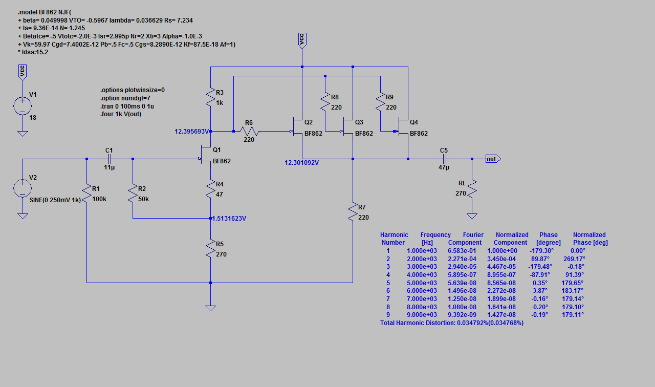
At modest 500mV p-p ouput levels, THD is only 0.014%.
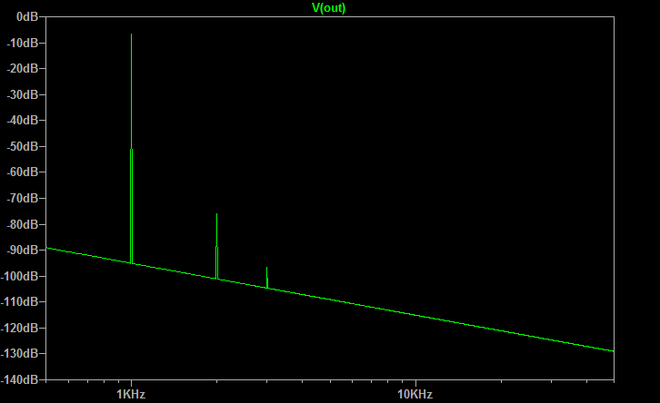
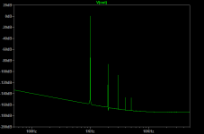
Whereas, I am not sure the qnty 10 x BF862 amp is buying much more (0.003% THD), but a HD profile that is not as pleasing:

Attachments
Last edited:
How is your amp build coming along? You should have sound by now.
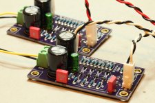
I do. They sound very good, very promising indeed. Still just boards on a bench with a lab supply and rigged wiring, so no lengthy listening tests yet. No measurements either. Will have time this weekend to take care of that and invest some serious listening time, especially late at night when the house is quiet.
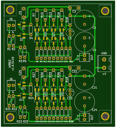
Binned the jfets and managed a group of 16 in the 14.50mA to 14.99mA range. After assembly, they measure between 14.50 and 14.99mA across the 1R resistor. So I didn't change the source resistors, they remain at 1R. The parts get comfortably warm, I'd guess 25-30C, but nowhere near hot. Have plans to measure that this weekend.
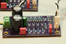
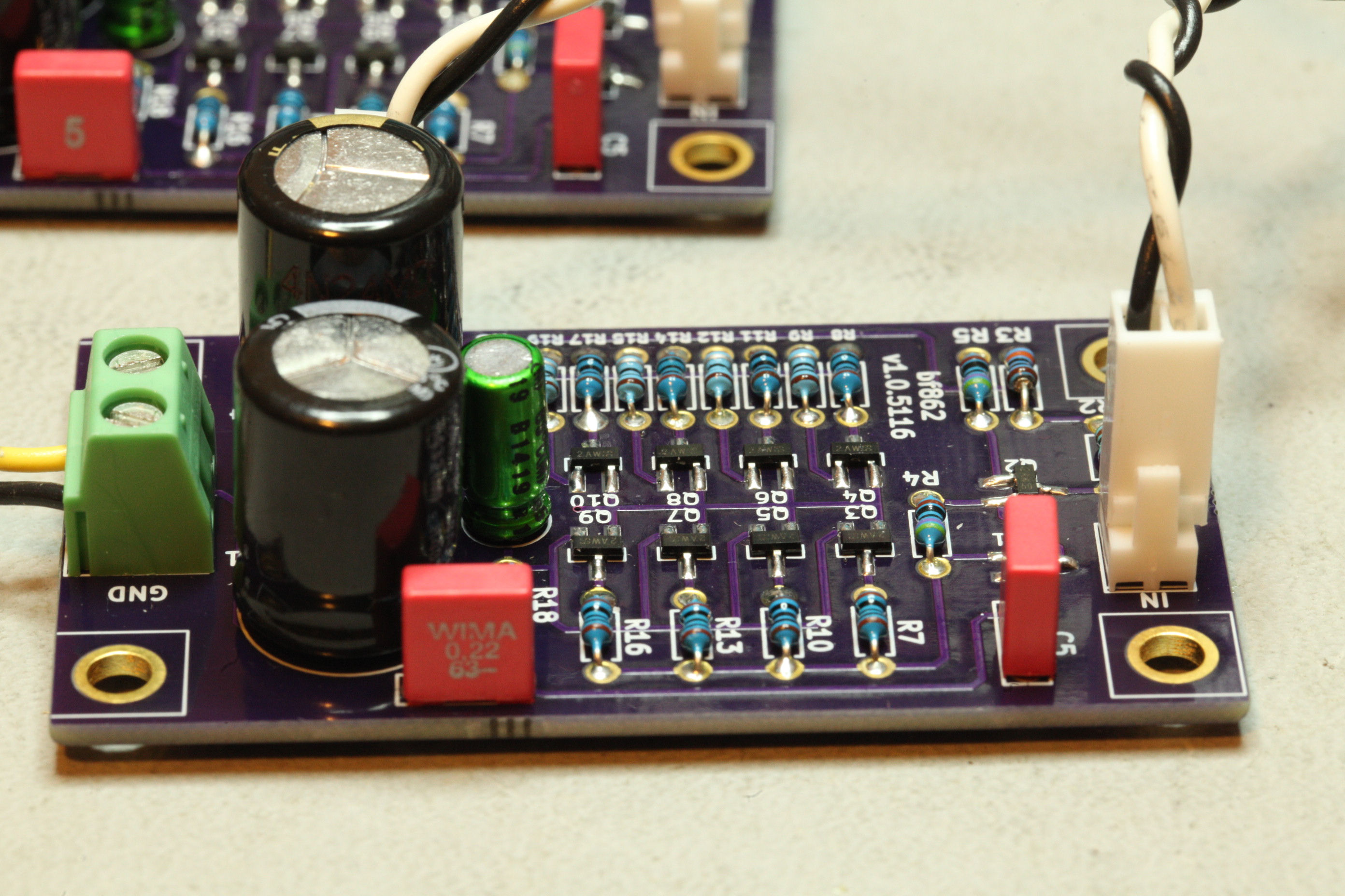
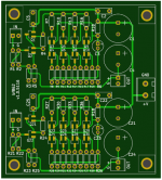
Pics of running bards on the bench.
Will post gerbs if anybody is interested. Yos can order 3 (2 required for stereo) from OSH Park for $18.95.
Attachments
I do. They sound very good, very promising indeed. Still just boards on a bench with a lab supply and rigged wiring, so no lengthy listening tests yet. No measurements either. Will have time this weekend to take care of that and invest some serious listening time, especially late at night when the house is quiet.
Binned the jfets and managed a group of 16 in the 14.50mA to 14.99mA range. After assembly, they measure between 14.50 and 14.99mA across the 1R resistor. So I didn't change the source resistors, they remain at 1R. The parts get comfortably warm, I'd guess 25-30C, but nowhere near hot. Have plans to measure that this weekend.
Pics of running bards on the bench.
Will post gerbs if anybody is interested. Yos can order 3 (2 required for stereo) from OSH Park for $18.95.
Beautiful work. Nice! What is size of board?
Yes, please post Gerbers.
Thanks,
X
Yes, please post Gerbers.
Thanks,
X
Board size is 2.6" x 1.4" each.
Attachments
Board size is 2.6" x 1.4" each.
Thank you. If it wouldn't be too much trouble, can you please provide a Gerber where both channels are combined into a single board (stereo) such that board size is about 2.6in x 2.8in ea? Most PCB houses have same charge for boards under 100mm square and it would be more economical to get stereo boards this way. You could even add some space and partial perf cuts to allow user option of breaking off into two separate boards if they wished.
Thanks,
X
Thank you. If it wouldn't be too much trouble, can you please provide a Gerber where both channels are combined into a single board (stereo) such that board size is about 2.6in x 2.8in ea?
Thanks,
X
Can do. One power connector or two?
Two connectors to keep as "monoblocks" for those interested in extreme stereo separation between channels. Also keeps it easy for you, and allows break apart smaller boards as option.
Thank you !
Thank you !
You could even add some space and partial perf cuts to allow user option of breaking off into two separate boards if they wished.
As far as I have seen, most chinese PCB fabs will recognize such board as a panel and will increase the price by $10 or so.
As far as I have seen, most chinese PCB fabs will recognize such board as a panel and will increase the price by $10 or so.
Is it the perf cuts that are the issue or the fact that it is same layout side by side? Does this require then a common power connector to alleviate the dual panel business?
As I understood, it is the clear indication of separate boards (even uncut) on one PCB no matter whether of identical or different designs which makes them suspicious.
So two monoblocks on one board counts as two boards no matter what? But if they are connected with one power supply with leads going to two boards, that can't be true because separating them makes them not functional.
So, I guess I will request Mlackey to make a single power connect please. 🙂
So, I guess I will request Mlackey to make a single power connect please. 🙂
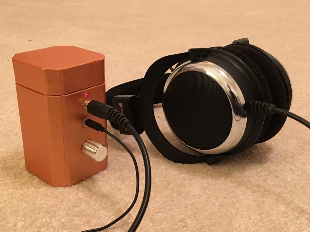
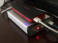
It really is portable now
Some new developmnts: my 10 JFET head amp is indeed operable from a Li-ion 5v battery pack. I tried using a 5v USB style 10,000mAhr battery pack earlier but could not get any bass. Just yesterday, my amp started running a lot cooler as in hardly any noticeable heat output on the case. It still sounded Ok so I took it apart to investigate why cooler? I thought maybe several of the FET legs were bad or something. Anyhow, I discovered that I had a small solder bridge across one of the main output JFETs (between D and S) and it was basically shorted and drawing huge current. After running hot for a week now, it burned itself out and self-resolved. I went in and reflowed the solder joints and remeasured overall current in both channels. They matched and total draw is about 134mA at 18.25v. This short was causing unusually high current draw before and as a result, the 2A 5v USB battery could not keep up with it. The amp is not at all warm now and I estimated a power consumption of about 3.3w including the DC-DC converter and cap multiplier. I decided to try the portable 5v Li-ion battery again and now it works like a champ. Superb bass authority - nice sound. The 10,000mAhr battery at 5v needs to supply about 660mA for 3.3w. This would mean about a 15hr run time in portable mode. I have not done any endurance testing yet but will do so now. This will be interesting though because could mean ability for a class A headphone listening on a long flight from US to Asia. These XL6009 DC DC converters are a great option for 18v requirement on SE class A amps.

The lower power draw of the 4 JFET amp would mean about a 40hr run time! (hard to believe so need to check how well the 10,000mAhr rating really holds up)
I am using this battery pack ($14):
https://www.amazon.com/KMASHI-10000mAh-Universal-External-Power/dp/B00JM59JPG
Some new developmnts: my 10 JFET head amp is indeed operable from a Li-ion 5v battery pack. I tried using a 5v USB style 10,000mAhr battery pack earlier but could not get any bass. Just yesterday, my amp started running a lot cooler as in hardly any noticeable heat output on the case. It still sounded Ok so I took it apart to investigate why cooler? I thought maybe several of the FET legs were bad or something. Anyhow, I discovered that I had a small solder bridge across one of the main output JFETs (between D and S) and it was basically shorted and drawing huge current. After running hot for a week now, it burned itself out and self-resolved. I went in and reflowed the solder joints and remeasured overall current in both channels. They matched and total draw is about 134mA at 18.25v. This short was causing unusually high current draw before and as a result, the 2A 5v USB battery could not keep up with it. The amp is not at all warm now and I estimated a power consumption of about 3.3w including the DC-DC converter and cap multiplier. I decided to try the portable 5v Li-ion battery again and now it works like a champ. Superb bass authority - nice sound. The 10,000mAhr battery at 5v needs to supply about 660mA for 3.3w. This would mean about a 15hr run time in portable mode. I have not done any endurance testing yet but will do so now. This will be interesting though because could mean ability for a class A headphone listening on a long flight from US to Asia. These XL6009 DC DC converters are a great option for 18v requirement on SE class A amps.
The lower power draw of the 4 JFET amp would mean about a 40hr run time! (hard to believe so need to check how well the 10,000mAhr rating really holds up)
I am using this battery pack ($14):
https://www.amazon.com/KMASHI-10000mAh-Universal-External-Power/dp/B00JM59JPG
Attachments
Last edited:
So, I guess I will request Mlackey to make a single power connect please. 🙂
Can do. In order to make them appear as "one" I will fix up the layout so there is just one power connector, four mounting holes (one in each corner), a single common ground plane, and change the reference designators so they differ between the two halves. Since there are no off-board parts I could "mirror" one side so the two halves are mirror images of one another.
Sound good?
Hi Mlackey,
Sounds great - thanks so much. Hope it's not creating too much work for you.
Cheers,
X
Sounds great - thanks so much. Hope it's not creating too much work for you.
Cheers,
X
gerbs
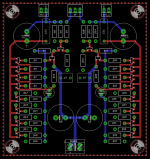
Here are gerbs for a dual board. I cannot "mirror" the image without serious layout changes. Which means untested circuit changes. and I didn't consider that initially. Since I have no plans to build this, I don't feel comfortable doing that.
All gerbers are in the zip file. I use "gcpreview" to check the gerbs before sending them out. It's free and it's good, but there are others. I've imported the gerbs into gcpreview and then saved them in a gwk project file. I had to change the extension to txt to get them uploaded, so change the file suffix from txt to gwk, and then open that with gcpreview to view the gerbers. The gerber naming conventions are those expected by OSH Park, but I'll provide more info if needed.
Check these out and see if they will work for you.
Attachments
Thanks Mlackey. If anyone is interested in a GB for this stereo board let me know. If I can get 5 people to go for two boards ea (two complete stereo systems) that would be critical mass. Cost includes shipping and will be $15 for CONUS and $22 for anywhere else in the world.
Attachments
Last edited:
Just modify the traces to place a couple of dummy traces across the join. These get "cut" before assembly.As I understood, it is the clear indication of separate boards (even uncut) on one PCB no matter whether of identical or different designs which makes them suspicious.
Add power input pads to both halves of the PCB. The interconnections between the two sets become the dummy traces.
Last edited:
Do not mirror a good layout PCB. Mirroring will change the loop areas and may impair performance.Here are gerbs for a dual board. I cannot "mirror" the image without serious layout changes. ...............
GB LIST - edit list to add name
Just reply with quotes to this post and add your name to the GB if interested. Please do it via list here rather than PM's.
- one member from PM has said he is interested in 2 boards
Thanks Mlackey. If anyone is interested in a GB for this stereo board let me know. If I can get 5 people to go for two boards ea (two complete stereo systems) that would be critical mass. Cost includes shipping and will be $15 for CONUS and $22 for anywhere else in the world.
Just reply with quotes to this post and add your name to the GB if interested. Please do it via list here rather than PM's.
- one member from PM has said he is interested in 2 boards
Do not mirror a good layout PCB. Mirroring will change the loop areas and may impair performance.
Uh oh... 😱
Any advice on my layout? Should I redo it non-mirrored?
Attachments
- Home
- Amplifiers
- Headphone Systems
- BF862 based SE Class A Headamp without the HEAT