I had WCF as option in Iron Pumpkin and several amps I made with autoformer gain
in the end, I deleted that option, finally not liking sonic imprint of it ..... it is somewhat better than straight buffer only on tougher loads - dunno - headphones maybe ..... but with more common/lighter loads, straight buffer is better for my ears
in the end, I deleted that option, finally not liking sonic imprint of it ..... it is somewhat better than straight buffer only on tougher loads - dunno - headphones maybe ..... but with more common/lighter loads, straight buffer is better for my ears
Thanks, ZM. 5,000pF of the THF-51S seems a tough load, perhaps I will try parallel JFET source follower with CCS load too as in your Singing Bush amplifier and see what the ears have to say.
complementary or not, pure grunt is what you need there
though, try whatever you meant to try, your ears must be pleased, not mine
though, try whatever you meant to try, your ears must be pleased, not mine
Based on this article I bought the A range Toshiba 2SJ74 matched quad form Punkydawg for my ACP+. ($35 vs $50).
Not so high and likely series regulated, but I have not gotten to that level of detail yet, just setting the stage and generating some ideas while the Tokin SIT are still available. The project queue is two or three amplifiers long at the moment, have to finish a doozy of a tube build first.
...perhaps I will try parallel JFET source follower with CCS load...
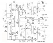
You could try the Sony front end.
Attachments
I bought some 2SK170s a few years ago from a local supplier. Their Idss values all measured above 10mA – so I assumed they are either fake or V grade.
Are there any uses or builds for the V grade jfets?
Are there any uses or builds for the V grade jfets?
Could be Bl's at the top of the curve, but likely V's. You can tell the difference in
that the transconductance is quite a bit higher than the fakes.
that the transconductance is quite a bit higher than the fakes.
example - Aleph J - so wherever biased with CCS - grade pretty much irrelevant (in all directions, as Pa did show in this article)
where biased with source resistor - you must take in account influence of said resistor on degeneration (so gain) and Rout od stage (if buffer is in question)
where biased with source resistor - you must take in account influence of said resistor on degeneration (so gain) and Rout od stage (if buffer is in question)
As mentioned already in the article, the follower circuits published by Borbely were running at Idss.
JFETs: The New Frontier, Part 2 | audioXpress
That always means that when driving a load, the JFETs will going into positive bias (Vgs>0 for N-JFET, and vice versa).
The questions is how far can you go.
It is known that the gate-source of an N-JFET behaves like a P-N junction.
In theory, as long as Vgs < 0.6V, the gate will not conduct.
Beyond that, the only thing that will limit gate current is the gate resistor (+ source impedance).
Assuming you are willing to take full risk, the extra current you will get beyond Idss is given by (approximately) :
0.6V x Yfs at Idss
For a typical 2Sk170BL, that would be ~14mA.
For a typical 2SK209GR, however, that would only be 9mA.
For other JFETs e.g. those Jxxx types, they might be just 6mA or less.
And of course, it all depends on how much risk you want to take.
I normally do not want to go beyond 1/5 of the above.
But then my name is not Pass.
😉
Cheers,
Patrick
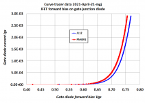
I just wandered into my workshop and put a couple of Nchannel JFETs on the curve tracer. At room temperature, this is how much current flows into the gate of each JFET, when its gate-to-source PN junction is forward biased. Reminder: for an Nchannel device, the gate diode is forward biased when Vgs>0 .
Notice that the two curves are not identical. Different JFETs have different gate diode forward bias behavior. It's not a big surprise.
Also attached is the curve tracer raw data if you want to experiment with it. Maybe you want a semilog plot? I recommend you assume this fixture plus these choices of curve tracer setup options, probably has a "noise floor" around 1E-7 amperes. Thus all reported "measured data" points below the floor, are pure noise.
_
Attachments
Many thanks for the measurements.
So at 0.5V, the gate current is less than 1µA, which I consider acceptable.
At 0.6V, it already jumps to ~10µA.
0.6V is for me a good value to set as absolute limit.
Cheers,
Patrick
So at 0.5V, the gate current is less than 1µA, which I consider acceptable.
At 0.6V, it already jumps to ~10µA.
0.6V is for me a good value to set as absolute limit.
Cheers,
Patrick
Let's look at another JFET also used in audio circuits, namely 2N5457/5460, or their SMD equivalent.
Typically, Idss is 3mA, and Yfs is 3mS.
For 0.6V positive bias for Vgs, the increase in drain current is less than 2mA, before the gate starts to conduct.
You certainly do not want to use those to drive a 1k load.
Cheers,
Patrick
Typically, Idss is 3mA, and Yfs is 3mS.
For 0.6V positive bias for Vgs, the increase in drain current is less than 2mA, before the gate starts to conduct.
You certainly do not want to use those to drive a 1k load.
Cheers,
Patrick
I bought some 2SK170s a few years ago from a local supplier. Their Idss values all measured above 10mA – so I assumed they are either fake or V grade.
Are there any uses or builds for the V grade jfets?
Surely there is a letter on them indicating the idss range, why the guess work?
My guess would be fakes unless you bought them a long time ago from Avnet
- Home
- Amplifiers
- Pass Labs
- Beyond the J Fringe