Papa,
Very cool. Necessity, in this case scarcity, is the mother of all....something or another. 😀
Very cool. Necessity, in this case scarcity, is the mother of all....something or another. 😀

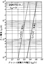
This chart is from an old thread and should give some indication on how far you can forward-bias before gate current becomes an issue. The solid line for room temperature is measured, the dotted line is supposedly calculated:
Attachments
This chart is from an old thread and should give some indication on how far you can forward-bias before gate current becomes an issue. The solid line for room temperature is measured, the dotted line is supposedly calculated:
Excellent graphic. Member PRR posted similar one in another forum that I relied on.

> +0.3V for 1nA gate current ?
Do we even care about 1nA?
Assuming about 1V signal, 1nA is like 1V/1nA= 1,000MegOhms.
Condenser mike head-amps worry about kilo-Megs. Tube guitar amps assume 200K happens everywhere.
If we assume 1Meg is generally no big deal, that is 1,000X less than 1,000Meg. Current rises 10X for about 60mV of voltage. So we could go 180mV higher. Assuming 350mV, now we can be 530mV. (Or we could just reference the uA line, which seems to hit at 520mV.)
Assume a gate capacitance of 50pF. Assume an input signal of magnitude 3 volts, with a slew rate of 25 volts per microsecond. Then
I_charge_the_gate_cap = (50 pF) * (3.0 volts) / (0.12 usec) = 1.25 milliamps
Assume we want the "error term" due to gate diode forward current, to be 120dB below the signal current of 1.25 mA. Then I_diode_forward = 1.25 nanoamps.
(At lower input signal magnitudes, the amount of gate forward bias decreases proportionally)
_
Last edited:
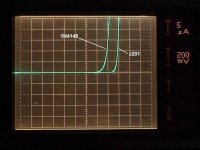
Here is a comparison of Gate current on a JFET (Drain and Source shorted) and forward current of a small signal diode. You can see that the JFET Gate stays off for significantly more Voltage than the diode. Center of the screen is zero Voltage (horizontal 0.2V/div) and zero current (vertical 5uA/div).
Attachments
- Home
- Amplifiers
- Pass Labs
- Beyond the J Fringe