Attachments
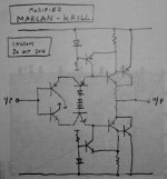
In the attachement the DC conditions in my simulation for that circuit (between 2N3773 and 2N3055 no difference to observe).
The p-spice modell of 2N3773 I have download from
ON Semiconductor
It is also possible to operate it in a high bias mode:
By pushing the Iq to ~200mA, Q1 never turns off completely, and the result is a very soft class AB operation, and a distortion down to less than 0.1%.
This is somewhat counter-intuitive, because in a conventional class B topology, widening the crossover region to that extent would increase the THD by gm doubling, but here, the Iq servo keeps things under control.
Attachments
Hi,
if both upper and lower devices actively control the output current, then the amplifier is effectively operating in ClassA.
While the amplifier is operating in ClassA, gm doubling cannot happen.
It's when a pair of active devices hand over to a single device for higher output currents that the phenomenon occurs. Or more precisely it's when an inactive device is given back it's active role that gm doubling can occur, if the bias has been set up incorrectly.
It matters not a jot that the inactive device is passing zero current or a near constant of few uA or a few tens of uA. If it is not actively controlling the output current then it handed that responsibility over to it's partner, i.e. it has moved from ClassA operation to ClassAB operation.
Last edited:
Hi,
if both upper and lower devices actively control the output current, then the amplifier is effectively operating in ClassA.
While the amplifier is operating in ClassA, gm doubling cannot happen.
It's when a pair of active devices hand over to a single device for higher output currents that the phenomenon occurs. Or more precisely it's when an inactive device is given back it's active role that gm doubling can occur, if the bias has been set up incorrectly.
It matters not a jot that the inactive device is passing zero current or a near constant of few uA or a few tens of uA. If it is not actively controlling the output current then it handed that responsibility over to it's partner, i.e. it has moved from ClassA operation to ClassAB operation.
Indeed, but here, there are times when Q1 alone is active, and this should cause even order distortions, but this is not the case.
Replacing the input transistor by a composite increases the input impedance to ~6 Meg, and reduces further the THD:
Attachments
It is also possible to operate it in a high bias mode:
By pushing the Iq to ~200mA, Q1 never turns off completely, and the result is a very soft class AB operation, and a distortion down to less than 0.1%.
This is somewhat counter-intuitive, because in a conventional class B topology, widening the crossover region to that extent would increase the THD by gm doubling, but here, the Iq servo keeps things under control.
At whole very interesting. If I have time, I will test the sound character. Why is despite Iq servo a thermal compensation necessary? In the attachement both circuits to compare the DC conditions
frominteresting topic. I recall to a special circuit in the German magazine "Funkschau" (diy power amp project approx. 1965) concerning bias stabilization for 2N3055 Circlotron. In the next time I will check old stuff and if I find this article, I will report about that circuit;
http://www.diyaudio.com/forums/soli...polar-transistor-circlotrons.html#post2337331
the second attachement (second circuit) shows the buffer stage and the exactly title and magazine number.
Concerning the temperature compensation was follow to read (translate in english from me):
By the CSPP topology there is no DC feedback (in opposite to normal true complementary push pull darlington or triplet BjT power follower). Therefore this kind of temperature compensation (NTC resistors) was used.
The first circuit with Sziklai-darlington is an idea from me - more easy to find appropriate thermal compensation about the source resistance.
Attachments
Last edited:
Member
Joined 2009
Paid Member
hi
how about Aikrill or Krillkido?😀
I think this has a lot to recommend it. I was thinking of a JFET input stage as an alternative to a tube and your design here does exactly that. I like it a lot.
Do you propose this out of academic interest or do you have interest in building it ?
gonna build
building:
from long time I was searching for something as good as tubes but without the glass and excessive heat.
aikido jfet voltage gain stage does it, I am sure that will sound perfect (the circuit is simplified).
the output buffer runs in flat a class and should be ok. I read from Broskie's blog that direct coupled speaker is similar to ac coupled because of way of using power supply capacitors - ac coupled means less trouble regarding thermal stability and no dc offset control is needed.
One worries me in diamond output buffer: symetrical limiting caused more odd harmonics...
Do you propose this out of academic interest or do you have interest in building it ?
building:
from long time I was searching for something as good as tubes but without the glass and excessive heat.
aikido jfet voltage gain stage does it, I am sure that will sound perfect (the circuit is simplified).
the output buffer runs in flat a class and should be ok. I read from Broskie's blog that direct coupled speaker is similar to ac coupled because of way of using power supply capacitors - ac coupled means less trouble regarding thermal stability and no dc offset control is needed.
One worries me in diamond output buffer: symetrical limiting caused more odd harmonics...
At whole very interesting. If I have time, I will test the sound character. Why is despite Iq servo a thermal compensation necessary?
There are no emitter degeneration resistors, and unlike a JLH f.e., it operates in class B, and has room for thermal runaway.
Perhaps less than a conventional complementary PP where it can be extremely brutal, but enough to run into troubles.
The servo operates on a relatively small range, and is not sufficient to accomodate wide temperature variations.
Last edited:
another ab buffer with jfet aikido
another buffer approach,
taken from the site evolve power amplifiers Trans_linear_Bias
should I call it aikvolve or evkido no matters🙂
again this buffer worries me: symetrical limiting caused more odd harmonics, you can see it at higher levels like 15Vpp. More idle current helps a LOT, odd harmonics dissapearing but my intention was the radiators only warm...🙄
anyway with the idle ~80mA at 10Vpp only odd harmonics are little higher than at 1Vpp
Attachments
Last edited:
Member
Joined 2009
Paid Member
Symmetrical output doesn't 'cause' odd harmonics per-se, but it does a good job of canceling even harmonics so that the odd harmonics are left as the dominant signature. I wouldn't be too concerned yet, best build it and then worry if you need to tweak it.
Thank you for this comment. What happens regarded thermal behaviour, if I use sziklai darlingtons in the power stage? Perhaps in this case the control range of servo is enough.There are no emitter degeneration resistors, and unlike a JLH f.e., it operates in class B, and has room for thermal runaway.
Perhaps less than a conventional complementary PP where it can be extremely brutal, but enough to run into troubles.
The servo operates on a relatively small range, and is not sufficient to accomodate wide temperature variations.
For both resistors between the base and emitter of Q1b/2b I choice this value to get the same whole idle current than circuit without Sziklai.
Attention !!! Dont try to build this circuit, because there are the risc of oscillation and damaged tweeters (no compensation elements was introduced !!! )
Attachments
Last edited:
Thank you for this comment. What happens regarded thermal behaviour, if I use sziklai darlingtons in the power stage? Perhaps in this case the control range of servo is enough.
For both resistors between the base and emitter of Q1b/2b I choice this value to get the same whole idle current than circuit without Sziklai.
I don't think that using Sziklai would influence very much the range of the servo: it is dictated by the ratio of Ic(Q3) to Ic(Q5), and there is a limit on how low Ic(Q3) can go: it has to be sufficient to drive the upper output transistor by itself.
Member
Joined 2009
Paid Member
My pleasure.
Any questions?
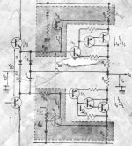
Q1 and D3 form a N-type LTP. Q2 and D2 form a P-type LTP. Q3 and Q4 each represent VAS for each opamp. They are loaded on each other, fully symmetrically. I.e. it is a complementary fully symmetrical opamp with 100% negative feedback.
For better linearity and thermal stability D1+R5/Q3R9 in the upper half and corresponding parts in the lower part form current mirrors.
Long tails are shortened intentionally: they are calculated for peak output current on max swing when the half in in class B phase. It prevents both hard clipping and output transistors' damage when output is overloaded. Don't apply GNFB around this stage, otherwise you will loose soft clipping!
You can turn it into class A symmetrical output stage: just remove R1,R2,D4,D5 and decrease R3 and R4 values.
I've redrawn the top half of this output in a format that matches your description. Now I see it. Very clever - and quite fun to make the leap from your first schematic to something more recognizable. There's so much to see in this design and lots of potential for playing with it. It's possibly a novel way to look at the CFP.
Attachments

Last edited:
Then I have yet only one possibility in mind: The introduce of emitter resistors for the output bjt's and using a lot of this units as whole circuit in parallel mode.I don't think that using Sziklai would influence very much the range of the servo: it is dictated by the ratio of Ic(Q3) to Ic(Q5), and there is a limit on how low Ic(Q3) can go: it has to be sufficient to drive the upper output transistor by itself.
But the question is, what value must have the emitter resistor at least to get full servo funktion.
Thank you for create this schematic. Very interesting detail is the introduce of serial network consist of R1 and D4 between the emitters of differential input amp and GND. This approach I have never seen before in a commercial amplifier circuit.I've redrawn the top half of this output in a format that matches your description. Now I see it. Very clever - and quite fun to make the leap from your first schematic to something more recognizable. There's so much to see in this design and lots of potential for playing with it. It's possibly a novel way to look at the CFP.
Last edited:
Member
Joined 2009
Paid Member
Thank you for create this schematic.
my pleasure.
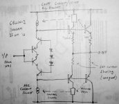
Now, it's time to combine some of the different thoughts I've been pursuing, such as the auto-bias thread [ http://www.diyaudio.com/forums/solid-state/145013-variable-operating-biass-output.html ] and my decision to go the Diamond Buffer route for my CELLINI-2 amplifier [ http://www.diyaudio.com/forums/tubes-valves/174889-cellini-2-hybrid.html ] which needs a no-feedback ClassAB buffer (the subject of this thread).
What I want is the means to control the bias from both the perspective of minimizing power dissipation without 'starving' the output and in terms of thermal stability.
Because I have imposed some limitations e.g. - no feedback it means no error correction. It also means that I can't suffer a large resistors at the output to provide current sense elements that might be used for bias control since they will increase the output impedance and there is no feedback to pull it back down.
So I'm thinking of using two pairs of complementary output devices with unequal current sharing. See the attached sketch. The main output devices will be unfettered (and 'hot') but in parallel with them is another pair which will run cooler and include a collector load that provides a means to monitor the current through them and therefore, through the amplifier output.
I figure that I get more measurement sensitivity if the collector load resistor is large, but this introduces a drop in supply voltage to the output device and attendant distortion. So I'm wondering if a current source could be used here instead. I'd then tap off the collector of this output device a measure of output current which is then used to control the bias current of the Diamond's drivers.
If done carefully it should also protect the output from over-current as in Nelson Pass F5 and the possibility to provide some dc servo action ????
Attachments
Member
Joined 2009
Paid Member
Now we will soon get some really wise guy coming here and discard Sziklai output.
Saying it is prone to oscillate.
Rubbish!
This is no reason against.
Because any amplifier, with any output, can oscillate.
We see this happen all the time under construction.
No. It is all about doing it right.
Whether we use the terrific Sziklai configuration or not.
Regards 🙂 Lineup
Lineup, what precautions / approach do you take to avoid parasitic oscillations with the Sziklai output ?
did you see D. Self book where he looks at distortion of Sziklai vs EFII and finds that at low power (1W or lower) that the EFII has less distortion ?
p.s. I also like the Sziklai, very elegant topology.
Last edited:
Member
Joined 2009
Paid Member
OK, now I 'smell' something interesting. If I take a look at my notes from two posts back and compare with Margan it suggests some similarities with the control of bias and possible modification of switching behaviour...😎
see: http://www.diyaudio.com/forums/solid-state/122007-margan-non-switching-class-b.html#post1956690
see: http://www.diyaudio.com/forums/solid-state/122007-margan-non-switching-class-b.html#post1956690
Attachments
Last edited:
Member
Joined 2009
Paid Member
- Home
- Amplifiers
- Solid State
- Best topology for no-feedback ClassAB buffer ?