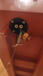
Ok, quick test with as close a network i could get on short noticeto the specs you calculated Allen. Mundorf 6.8ohm resistor + 0.5mH/0.49ohm coil. Well the LF are now deffinately in the room, the general balance is much better for sure, but i have noticed some new things in the sound that were new. That I must do more listening.
I have tried with only the resistor, that alone brought quite a bit of bottom end but kept the character fairly in tact. Adding the coil changed it a bit, somewher in the HF. Not sure what to make of it yet.
I have ordered now a few more resistors and coils to test (a "propper" bsc with a higher value inductor). Also on the way is a umik-1 mic, some neotech solidcore 24a wire and some audiigrade felt.
Looking forward to playing aroud, this is fun🙂
I will try soldering everything together ofc, not sure how much of an neg. impact just twisting stuff together has?
Attachments

I'm starting to dabble into Xsim, trying to get a feel how various components/values/networks behave. Most is as expected, but having a single resistor in series, like I have tried yesterday, seems to attenuate across the band equally - that is to say the shape of the FR plot does not change, merely moves "down" apropo the value of resistor used.
I have tested this yesterday and it resoulted in more bass (comparatively). It was rather obvious. Is this due to reduced damping factor, which allows the driver to "flabber" around more freely near its resonance, but Xsim software doesnt acount for?
I have tested this yesterday and it resoulted in more bass (comparatively). It was rather obvious. Is this due to reduced damping factor, which allows the driver to "flabber" around more freely near its resonance, but Xsim software doesnt acount for?

Yes, I've taken both the frd and zma files from another FR driver (Tangband). I know its not hte same, but the effect should be? Its what I could find. If you have both files available for fostex FE206En, please! Otherwise I also found FPGraphTracer, which I will try to use.
EDIT
Sorry, I really should have been more precise. Checking again now, the FR graph was showing only 100hz upwards, so I was missing the lower bass! That clears it up, thanks!
Also with the file you shared, I also see less attenuation towards top most FR (as driver impedance rises again).
EDIT
Sorry, I really should have been more precise. Checking again now, the FR graph was showing only 100hz upwards, so I was missing the lower bass! That clears it up, thanks!
Also with the file you shared, I also see less attenuation towards top most FR (as driver impedance rises again).
Last edited:
I sucessfully traced Fostex' FR graph for the BLH and ran a sim. Will do an actual measurement once the mic arrives.
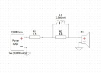
Grey - 1.5R (amp Rout)in series - IS THIS CORRECT?
Blue - 1.5R (amp) and 6.8R in series
Red - 1.5R (amp) and (6.8R+0.5mH paralleled) in series
Green - 1.5R (amp) and (6.8R+2.2mH paralleled) in series - to try next
Listening impressions Blue vs Red. Im quite sure I prefer Blue (just the resistor in series). Adding the small inductor brings the upper midrange back up, comparetively kills the just the highs. Sound is muddier and darker, but overall just feels less balanced. Note I'm listening ca 20-30' off axis, which brings the topmost range down anyway.
Next to try is a higher value inductor 2.2mH in paralel with the resistor, as calculated for BSC. That seems to tame the upper midrange more.
What do you think? Am I doing this right?
Attachments
Well, it makes sense that the coil passes low, not high so it's lower resistance at low frequencies (approaching it's DCR), compared to the 6R8 resistor it's in parallel with, means that having the coil in place brings up the lower frequencies relative to just the series added 6R8. But, is it causing a phase shift in the signals it passes? Is that muddying up the low frequencies? Dunno.
The impedance file is the one that allows you to see the changes that the crossover components make. I've been showing the filter effects without a response file, in a way that makes them easier to see.
Of course the response file allows you to see it all in context. Remember that it doesn't yet cover extra effects like the baffle.
Of course the response file allows you to see it all in context. Remember that it doesn't yet cover extra effects like the baffle.
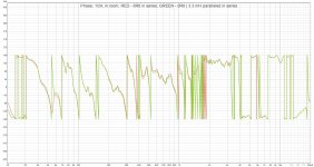
Yes I got that Allen, of course this is all just me learning and trying to get a feel for things. I'm looking forward to doing some real measurements soon when the mic arrives. I'm including the impedance image below, same colors. But to be frank, im not sure what to make of it. Can you chime in?
Also the FR i plotted from Fostex' original chart of driver in this very same enclosure. Shouldn't baffle step thus already be accounted for?
ranshdow, the phase seems to be "shifting", but not dramatically so to my eye. Not sure what to make of that either. 🙂
Also the FR i plotted from Fostex' original chart of driver in this very same enclosure. Shouldn't baffle step thus already be accounted for?
ranshdow, the phase seems to be "shifting", but not dramatically so to my eye. Not sure what to make of that either. 🙂
Attachments

There's probably not anything to make of it. If I'm reading it correctly this is what the amp will see, and they're all usable. The phase varies with the response variations, no surprise there. The different impedances represent attempts to vary the response, as expected, but that specific information is obscured in this point of view.
Increase bass output?
I used an unmodified/unfiltered FE206E in a BLH with an SEAS 8” passive radiator on the back side of the compression chamber. It had the usual mid/HF response characteristics of the FE206E, but increased bass.
The layout of the horn was NOT like the Fostex horn designs (which made this use or a PR possible). This is conceptually/functionally like the factory recommended cabinet for the FE126E, that included a ported compression chamber, that vented just inside the mouth of that horn.
The passive radiator seemed to have no ill effects, though no measurements were made. I am just guessing, but I think it likely that the PR had an FS (resonance) of about 40-50hz. The compression chamber was something like 10 liters---also guessing wildly.
Most BLH designs are similar to the Fostex, so they would not accommodate a passive radiator on the compression chamber. Mine had the driver mounted on the wide side---facing forward---and the PR on the back.
This was around 2008 or 2010. I brought it to the Planet 10 DIYFEST near Victoria BC around that time (Do Dave/Chris remember this one?). They were surprised by the larger bass output of the speaker than that of other designs for the FE206E.
I remember the FE126E in it's Frugel-Horn was shown at DIYFEST to make more bass than the FE126E in my smaller,but similar, FE126E horn (with no PR).
Dave, had the FE206E been used in the Frugel-Horn at that time? It seems like a large FH would work well with the FE206E, though higher QTS drivers might be better suited.
Last edited by a moderator:
I had to go look for Joan, and I found her here:
https://www.audiocircle.com/index.php?topic=173266.0
I'd say overall she takes up about as much space as my build for the FE206E, but Joan likely has a better WAF, being narrower.
https://www.audiocircle.com/index.php?topic=173266.0
I'd say overall she takes up about as much space as my build for the FE206E, but Joan likely has a better WAF, being narrower.
Intresting idea with the passive radiator, but as you said, no-go in fostex' design. Perhaps two slim oval ones on the sides 🙂 probably to narrow to be worth it.
But now I think I have landed into "happy with bass" territory. I've now put a bigger 3.3mH coil in parallel with the 6R8 (in addition to 1.5 rout of ACA). That has brought the sub 300-400 ish Hz frequrncies up another 3db or so. Sounds fuller. So much so that i have even angled the boxes back in to maybe only 10'deg or so off axis. This added appreciatable detail, without beeing overpowering.
I have even measured with a calibrated mic now, and the smoothed out response is near flat from 40hz all the way up. I will include graphs when I get home.
Ofcourse there are still some local peaks and dips and the upper range is wild. But it feels like I can now move to phase two, tweaking the driver and enclosure/damping to smooth out the response.
But the real goal is to make it even more lively/live while making it smoother.
Color me shocked. I did not expect to hear a noticeable difference with the 24awg solid copper wire from cat5/6 cable but it’s definitely there. I’m not sure it’s what I’m looking for with this amp/speaker combo, but the effect on the sound is certainly noticeable and different.Skinny wire wouldn’t hurt either. What are you using now? A quick thing to try is grab some solid core CAT5/6 cable and strip out a pair of speaker cabled.
Same here! Did you use a single strand? How long? I used 5m pair per speaker (so 10m + and - wire), mine was 26awg. Measuring low resistances with a multimeter is a bit tricky, but with shorting/calibrating i got a measurement of 2.2 ohms (all 10m). Very noticable indeed, but that little wire was making me so nervous screwing it in and kids running around.Color me shocked. I did not expect to hear a noticeable difference with the 24awg solid copper wire from cat5/6 cable but it’s definitely there. I’m not sure it’s what I’m looking for with this amp/speaker combo, but the effect on the sound is certainly noticeable and different.
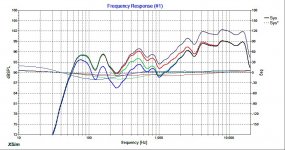
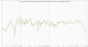
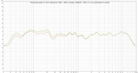
Here are the plots from my listening position, comments on the image. Recorded with a calibrated Umik-1 in REW. Its fairly consistent with what i got in Xsim, so im glad thats working. Now some questions to help me understand this better.
*note, speakers are only slightly toed out (5-10 deg off-axis from mic), ca. 3m away in ca.30 sqm room.
1. How does it look in general, what might be the biggest eye-sore, what might I try next?
2. That dip at 50Hz i believe must be room related, what do you think?
3. What can I do regarding that dip at ca. 300 Hz?
4. What can I learn from the phase plot?
5. Is there any other plot in REW I might want to take a closer look at at this stage?
Appreciated as always!
Next step will be experimentation with non-destructive mods, replacing the hookup wire, grounding the chassis and experimenting with damping. I got some 8mm acoustic felt and some 20mm acoustic felt on bitumen, self-adhering. I haven't any sand yet, but what can i expect by putting some of it in the driver chamber and reducing the volume there?
Attachments
Single strand ofc. I think mine are only about 2m each running back to each monoblock.Same here! Did you use a single strand? How long? I used 5m pair per speaker (so 10m + and - wire), mine was 26awg. Measuring low resistances with a multimeter is a bit tricky, but with shorting/calibrating i got a measurement of 2.2 ohms (all 10m). Very noticable indeed, but that little wire was making me so nervous screwing it in and kids running around.
Regarding your REW sweeps I agree the 50hz dip is likely room related and probably not something you’d notice 90% of the time. How do you like the sound?
- Home
- Loudspeakers
- Full Range
- Best Amp & cables for Fostex FE206En BLH