In short: the impedance of pin #15 is too high for input 10k/47uf low cut filter, it is slope curve from 200Hz. Increasing P34/40 to 100k and C34/35 4,7uf (I found only 10uf) solves the problem, but increases the sensitivity of the input buffer to interference. Perhaps a more reliable solution would be to use a VCOM buffer with 5-10ohm resistor on output. So far I haven't noticed a difference. See legend under pic..

Thanks! Very interesting to see how Vcom affects frequency response. Moreover, an explanation why an unstable Vcom could result to opamp failure.
Using a simulator I found a simple solution with VCOM oscillation. Place these additional parts as close as possible to the OPAMP output pin.

Here is how I did it in my soundcard. U1 at the left is CS4272. Pin #15 is terminated at C1=1μF and left alone. Vcom is created by R13/14 voltage divider and goes to U4 DC buffer. Please note R15/C17 at the input of U4. The output -blue highlighted trace- then goes straight to the analoge input buffer -opa1632 in this case.
Attachments
Hm.. seems like 1k neutralizes the essence of C18. I think length of trace from R13/14 to C17 is a good resistor for high frequencies.
Last edited:
R13/14 are 3k3. C18 is 470μF to shunt the ripple of the psu to ground. There is a similar circuit with higher values at the input of IC16 on Behringer. The mod in post #18 works with that and if the wire that shorts the two inputs is substituted for 1k resistor and 100nF cap to ground, it might made it possible to remove C49/51.
Hi all,
the chip crises seems to fade out.
So I started the search for a good available OPAMP again. I was lucky to get access to the APx555 over the weekend and tested some.
Here are the results for NE5532, OPA1662, OPA2210 and OPA2211. Gain is +10, and the ouput level +10dBV.
I designed a test board with through hole metal film resistores and DIL for the OPAMP. SOIC8 tested with adapters.
Any other recommendation for an OPAMP?
Alfred
Attachments


Good old bjt input NE5532 seems a bit noisy to the lower end. OPA2210/11 really shine! I don't know what is their input topology but Zin points to bjt. I wonder how they compare to to a jfet input like OPA1656.
there is a review of the QA403 at ELEKTOR.
https://www.elektormagazine.com/news/quantasylum-qa403-audio-analyzer-review
seems to be written by a very experienced engineer 😉
https://www.elektormagazine.com/news/quantasylum-qa403-audio-analyzer-review
seems to be written by a very experienced engineer 😉
Hi here all 🙂
I'am trying to create an autoranger/measurement interface for my Behringer soundcard with @MagicBus balanced mod.
This is kind of related to this Behringer thread, so I will post my protoboard and thought's here.
For the last 4-5 month's I was reading and testing a lot opamp stuff, and getting inspiration around the net regarding an autoranger, measurement interface etc...
I was scratching my head a lot to figure out what excatly I would need.
When I started out, there was actually none diy autoranger's out there, so I decided to do my own, take it or leave it...
My first goal was to proto some circuit which could actually sense the incomming voltage from the DUT, and when I was a newbee into this I started my own thread up HERE But I soon realized that I was too low on knowledge to really move on from there, but thank's for those who did help me a lot there.
Well there was an idea about using a rail to rail voltage (5vdc) opamp to feed the ADC (ADS1115 protoboard)

Reason I chose an external ADC instead of using the buildin's one on the ESP32 board Link!, is that the buildin is very hard to handle and I see it as unusable for such a project here. As soon as I had this ADC up and running I realized that I did the right choice, It's rock stable and a very low hysteresis can be used with it in the code.
Having this on a protoboard along with an active rectifier and a diff. to singleended opamp configuration next step was to do the attennuator input circuit.
Reading (again) a lot about this, I finally after several attempts, figured out howto with only 3 relay's creating an attenuator for -0db, -6, -12, -18, -24, -30. -36 and -42dB.
This along with an opamp buffer circuit was a milestone for me getting there.
I also needed some circuit protection which I also see on other circuit's out there, and ended up with using more or less the same circuit as the Valve wizard's soundcard interface uses. Link! I added a relay on my circuit to choose between using and not using this part, as I guessed it would add some sort of distortion.
Well, the Behringer is clipping around 1.2vac so I prototyped a circuit which could change gain on an instrumental opamp, spanning from a gain of 1.0 to 2.0, so that it should be possible to have the ranger target a voltage close to -3dB or whatever whished 🙂
It's for sure possible, but when having such a big proto there thing are starting to get very unstable ofcause.

I then had the idea to create some kind of motherboard, where the shall be provision for piggybagging the actual output circuit, which I find the most challenging part.
On this output card I will have the circuit to target to choosen output voltage along with some Bal. to SE and maybe visa/versa, I donne for sure yet.
So I designed this motherboard, hoping to have this right at first shoot 😉...Well I will not be surprised if I have to redo it, but so far I did test most of it good working.
On this motherboard I have the basic thing's (Attenuator, buffer, active rectifier, plugs for buttons, encoder and IIC display, that be LCD, oled or whatever.
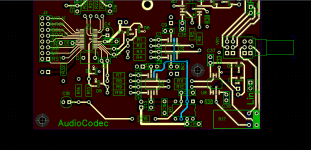
Last week i recieved it, it's rather big, fitting into a Hammond box with a PCB width of ~160mm. There are no PSU on the motherboard, only plugs/pins.

All resistors in the attenuator circuit and some in the protection is 400mW thinfilm 1206 one's, the only one not beeing a thinfilm one is R6, duo to I forgot to order it.
Rest of most of the parts is 0603 + 0805 SMD's.


The PCB frontside (there are a few parts on the backside)

I stuffed some of it up, and ran some spectrum's to see how it would look like.
I have attached pictures of.
EDIT Forgot the spectrums :


Now I need a little break.... 🙂 Next is to finish all the testing and then onto designing and prototyping the output card during the upcomming winther.
Edit, Edit... The LND150 SMD depl. mosfets are located on the backside, having footprints on the front for the TO92 part.
Jesper.
I'am trying to create an autoranger/measurement interface for my Behringer soundcard with @MagicBus balanced mod.
This is kind of related to this Behringer thread, so I will post my protoboard and thought's here.
For the last 4-5 month's I was reading and testing a lot opamp stuff, and getting inspiration around the net regarding an autoranger, measurement interface etc...
I was scratching my head a lot to figure out what excatly I would need.
When I started out, there was actually none diy autoranger's out there, so I decided to do my own, take it or leave it...
My first goal was to proto some circuit which could actually sense the incomming voltage from the DUT, and when I was a newbee into this I started my own thread up HERE But I soon realized that I was too low on knowledge to really move on from there, but thank's for those who did help me a lot there.
Well there was an idea about using a rail to rail voltage (5vdc) opamp to feed the ADC (ADS1115 protoboard)
Reason I chose an external ADC instead of using the buildin's one on the ESP32 board Link!, is that the buildin is very hard to handle and I see it as unusable for such a project here. As soon as I had this ADC up and running I realized that I did the right choice, It's rock stable and a very low hysteresis can be used with it in the code.
Having this on a protoboard along with an active rectifier and a diff. to singleended opamp configuration next step was to do the attennuator input circuit.
Reading (again) a lot about this, I finally after several attempts, figured out howto with only 3 relay's creating an attenuator for -0db, -6, -12, -18, -24, -30. -36 and -42dB.
This along with an opamp buffer circuit was a milestone for me getting there.
I also needed some circuit protection which I also see on other circuit's out there, and ended up with using more or less the same circuit as the Valve wizard's soundcard interface uses. Link! I added a relay on my circuit to choose between using and not using this part, as I guessed it would add some sort of distortion.
Well, the Behringer is clipping around 1.2vac so I prototyped a circuit which could change gain on an instrumental opamp, spanning from a gain of 1.0 to 2.0, so that it should be possible to have the ranger target a voltage close to -3dB or whatever whished 🙂
It's for sure possible, but when having such a big proto there thing are starting to get very unstable ofcause.
I then had the idea to create some kind of motherboard, where the shall be provision for piggybagging the actual output circuit, which I find the most challenging part.
On this output card I will have the circuit to target to choosen output voltage along with some Bal. to SE and maybe visa/versa, I donne for sure yet.
So I designed this motherboard, hoping to have this right at first shoot 😉...Well I will not be surprised if I have to redo it, but so far I did test most of it good working.
On this motherboard I have the basic thing's (Attenuator, buffer, active rectifier, plugs for buttons, encoder and IIC display, that be LCD, oled or whatever.
Last week i recieved it, it's rather big, fitting into a Hammond box with a PCB width of ~160mm. There are no PSU on the motherboard, only plugs/pins.
All resistors in the attenuator circuit and some in the protection is 400mW thinfilm 1206 one's, the only one not beeing a thinfilm one is R6, duo to I forgot to order it.
Rest of most of the parts is 0603 + 0805 SMD's.
The PCB frontside (there are a few parts on the backside)
I stuffed some of it up, and ran some spectrum's to see how it would look like.
I have attached pictures of.
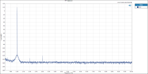
- 1kHz direct into Behringer
- 1kHz through my SupeRanger at -0dB
EDIT Forgot the spectrums :
Now I need a little break.... 🙂 Next is to finish all the testing and then onto designing and prototyping the output card during the upcomming winther.
Edit, Edit... The LND150 SMD depl. mosfets are located on the backside, having footprints on the front for the TO92 part.
Jesper.
Last edited:
Nice project, Jesper! FYI, there is an autoranger available on the internet on https://linearaudio.nl/la-autoranger, but the author did not publish the schematic. And the author also stopped taking new orders.
I considered building an autoranger for my DIY audio analyzer, but eventually chose rotary switches because, uhh, I was maybe a bit too lazy😉. I chose cheap rotary switches from Aliexpress, which, in hindsight, I regret having used. They are cheap, but you almost need a wrench to rotate them. And worse, the contact resistance is unstable. If I were to build an attenuator again, I would have used relays, just like AP does.
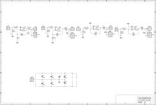
I agree with you about the too-high input resistance Pete Millett chose for the protection circuit, which adds noise. The Valve Wizzard solution with two MOSFETs seems quite elegant. AFAIK, in the older Audio Precision analyzers, a lightbulb limits the current. Instead of a lightbulb, I decided to use a 100R power resistor in series with a CMF-RL50A-10-0 resettable fuse. And, just like you did, clamp the voltage with zeners below the supply voltage of the op-amps. See attached schematic for your reference (R10...R13 are the protection resistors on the schematic). If my assumptions and simulations are right, the circuit should be able to handle mains voltages on the input, even in the most sensitive position (200mV full scale). Admittedly, I did not test the circuit up to that voltage...
Good luck and keep us posted!
I considered building an autoranger for my DIY audio analyzer, but eventually chose rotary switches because, uhh, I was maybe a bit too lazy😉. I chose cheap rotary switches from Aliexpress, which, in hindsight, I regret having used. They are cheap, but you almost need a wrench to rotate them. And worse, the contact resistance is unstable. If I were to build an attenuator again, I would have used relays, just like AP does.
I agree with you about the too-high input resistance Pete Millett chose for the protection circuit, which adds noise. The Valve Wizzard solution with two MOSFETs seems quite elegant. AFAIK, in the older Audio Precision analyzers, a lightbulb limits the current. Instead of a lightbulb, I decided to use a 100R power resistor in series with a CMF-RL50A-10-0 resettable fuse. And, just like you did, clamp the voltage with zeners below the supply voltage of the op-amps. See attached schematic for your reference (R10...R13 are the protection resistors on the schematic). If my assumptions and simulations are right, the circuit should be able to handle mains voltages on the input, even in the most sensitive position (200mV full scale). Admittedly, I did not test the circuit up to that voltage...
Good luck and keep us posted!
Attachments
Hi...
@jp8 Thank's for the word's... and I fully agree with you regarding the protection part.
When I wrote that none diy autoranger's was available, I also had the L|A Autoranger on mind 🙂
- And no it's not for sale anymore.
@MagicBus


Some better cabling and a temp. chassis :

The GND loop's are just a matter of schielding and Y grounding I now see... So I also needed to see this anyway before I would order the Hammond chassis.
If one look's carefully at the -0dB and the -6dB FFT there are some added noise at -6dB, but less at -12dB (not shown here).
I read somewhere that's this is duo to the resistorsizes when creating the -6dB attenuation (I mispelled attenuator on the PCB btw... 😵)
When using -6dB the two resistors will be the same (RL1 and RLG1 in parallel with RLT1 = 10K & 10K). It's something with the impedance seen by the opamp)
But the added distortion is <120dB so not sure it means that much?
Best thing is that I can elliminate most of the -6dB in my code, which along with everything else I do will be 100% shown and "opensource" which is the right spirit for everything diy 😎 Just needed to say this btw...
Also I must say, that this is only the basic motherboard with an op1656 buffer after the attenuator i measure on right now, there are no outputcard yet...
Comment's are very welcome...
Jesper.
@jp8 Thank's for the word's... and I fully agree with you regarding the protection part.
When I wrote that none diy autoranger's was available, I also had the L|A Autoranger on mind 🙂
- And no it's not for sale anymore.
@MagicBus
As you command :You just need to eliminate some ground noise.
Some better cabling and a temp. chassis :
The GND loop's are just a matter of schielding and Y grounding I now see... So I also needed to see this anyway before I would order the Hammond chassis.
If one look's carefully at the -0dB and the -6dB FFT there are some added noise at -6dB, but less at -12dB (not shown here).
I read somewhere that's this is duo to the resistorsizes when creating the -6dB attenuation (I mispelled attenuator on the PCB btw... 😵)
When using -6dB the two resistors will be the same (RL1 and RLG1 in parallel with RLT1 = 10K & 10K). It's something with the impedance seen by the opamp)
But the added distortion is <120dB so not sure it means that much?
Best thing is that I can elliminate most of the -6dB in my code, which along with everything else I do will be 100% shown and "opensource" which is the right spirit for everything diy 😎 Just needed to say this btw...
Also I must say, that this is only the basic motherboard with an op1656 buffer after the attenuator i measure on right now, there are no outputcard yet...
Comment's are very welcome...
Jesper.
👍Best thing is that I can elliminate most of the -6dB in my code, which along with everything else I do will be 100% shown and "opensource" which is the right spirit for everything diy 😎 Just needed to say this btw...

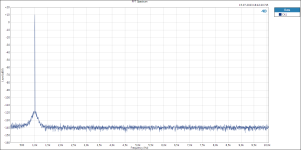
Below the 1kHz test signal no hum when with the aluminum tray. What is the remaining hash in the harmonics? Little op-amp instability maybe?
Hi @Salas
I'am not sure about that harmonics grass between the 2,3,4 etc... harmonics.
I made a provision for SMD capacitors on the board at the input buffer, but I did not solder in some, as I'am not sure about the value, or if it will help anything at all.
Also I did not (yet) know howto measure instability? I assume I must use my oscilloscope for this to see if the sine is clean and not ghosting?
Help appreciated here. I really wanna learn this 🙂
But we are also looking at the Behringer's limit here, the harmonics are from the Behringer, but the grass below -120dB is my SuperRanger.
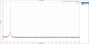
The 1kHz osc. I'am using is the Victor's, and when notched we reach much cleaner and lower THD's. (Se picture below)

1kHz ---> notch ---> Behringer

Below the 1kHz test signal no hum when with the aluminum tray. What is the remaining hash in the harmonics? Little op-amp instability maybe?
I'am not sure about that harmonics grass between the 2,3,4 etc... harmonics.
I made a provision for SMD capacitors on the board at the input buffer, but I did not solder in some, as I'am not sure about the value, or if it will help anything at all.
Also I did not (yet) know howto measure instability? I assume I must use my oscilloscope for this to see if the sine is clean and not ghosting?
Help appreciated here. I really wanna learn this 🙂
But we are also looking at the Behringer's limit here, the harmonics are from the Behringer, but the grass below -120dB is my SuperRanger.
The 1kHz osc. I'am using is the Victor's, and when notched we reach much cleaner and lower THD's. (Se picture below)
1kHz ---> notch ---> Behringer
With the oscilloscope you look directly for high frequency oscillation. AC coupled input selected and few mV vertical sensitivity. You run no test signal and you select faster and faster for horizontal time. Sometimes pressing auto mode can even catch it. When you run test signal, thickening of sinewave or squarewave as a whole or in portions can be a clue to something's wrong. Sometimes appearing at a certain region of signal volume or on all strengths. The HF oscillation itself can appear as a little sinewave or something more weird like a crooked sawtooth etc. In any case it must be something periodic to be an oscillation and not noise.
- Home
- Design & Build
- Equipment & Tools
- Behringer UMC 202HD for measurements