Moby said:Yes, I added that 332+332+332/15n in the air...
Maybe something like this can work. -16.5db attenuation, flat and with 10k of load....
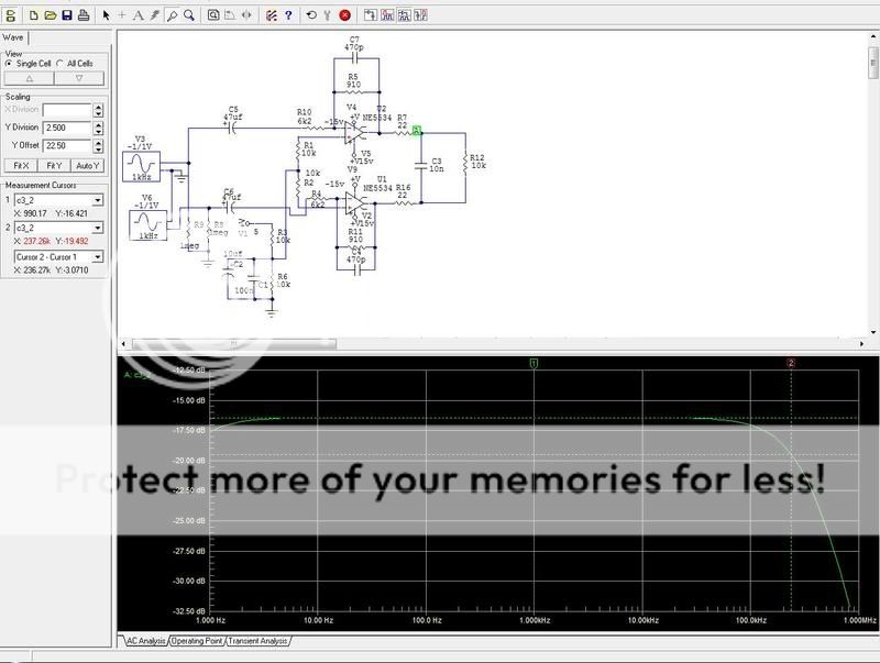
I would feel uncomfortable with that 10nF load at the opamp with only 22ohms in series. There is another circuit in the data sheet with 180 ohms series R's and smaller C. I would prefer that. Or even better, leave the 330 ohms series in the DSP board, delete the 330 ohms parallel and decrease the cap to keep the same cutoff freq.
Jan Didden
janneman said:Has anyone measured a fully stock unit, analog in -> analog out, all filters out, all levels 0dB? Maybe the stock unit isn't really flat?
Yes, I did, and it is flat.. I hope someone can verify 😉
Agree, its even better to op-amp to see bigger series resistor 180 sounds reasonablejanneman said:
I would feel uncomfortable with that 10nF load at the opamp with only 22ohms in series. There is another circuit in the data sheet with 180 ohms series R's and smaller C. I would prefer that. Or even better, leave the 330 ohms series in the DSP board, delete the 330 ohms parallel and decrease the cap to keep the same cutoff freq.
Jan Didden
😎
So now when we know that it's flat stock and without input shelving filter I can say that some of signal is definitely burned

The damn thing isn't such bad. You simply have to replace analog I/O board and to add SRC/clock board and you will be close to sonical 'heaven'. http://www.pilghamaudio.com/index.asp?pgid=55
Good luck!
Good luck!
Damn thing is great if you count that cost 220EU 😉 I already did clock, op-amps , caps, PSU, minireg upgrade. And It's really close to heaven for around 600EU in total😎
By using the right replacements you could have been a 'bit' closer at the same price. But you are on the right way and so there is headroom for further mods. Have fun!
oettle said:The frequency response of the stock unit is flat! Your so called 'measurement' is a simulation based on schematics but not real assembly of the input buffer PCB.
If the schematic used is correct, the simulation is correct within reasonable limits. In this case it would give the response within 0,1dB or so.
based on the findings, are we sure that the schematics that are floating around are correct ?
I am currently redesigning the input/output analog section to suit my personal needs, and wether a shelving filter is necessary or not makes everything a lot different.
hehe, well that makes a helluva difference if those components are NOT in place with regards to the frequency response of the buffer, as then it will of course be straight (except from the high frequency rollof caused by the pF caps)
that explains basically everything. Thanks!
Rickard picks up screwdriver and looks at his DCX2496...
and realize there is a lot of screws holding the connectors on the backplate to remove before he can inspect the underside of the PCB...
that explains basically everything. Thanks!
Rickard picks up screwdriver and looks at his DCX2496...
and realize there is a lot of screws holding the connectors on the backplate to remove before he can inspect the underside of the PCB...
oettle said:Sorry one typo. It's C90 not C89.
Big difference.. C90 being a 6.5" with 93dB sensitivitty and C89 only a 5" with... oh sorry!! You're talking about caps?
😉
😀
p.s. Hej Rickard!
/Peter
YES! JA!
I am not talking about Ceramic speaker elements here. Ceramic caps , possibly!!!
Do I know you from some other forum 😉 ?
I am not talking about Ceramic speaker elements here. Ceramic caps , possibly!!!
Do I know you from some other forum 😉 ?
oettle said:The schematics are correct, but C5-R2, C71-R103 and C89-R181 are not assembled.
That explains it. I wonder how accurate those schematics really are. How about those 330ohms and cap at the input of the ADC's, are they there?
Jan Didden
rikkitikkitavi said:YES! JA!
I am not talking about Ceramic speaker elements here. Ceramic caps , possibly!!!
Do I know you from some other forum 😉 ?
Well yes ACTUALLY you do! 😀
/Peter
Sh***t I have those c-r's. It looks like my unit is older revision :-(.oettle said:The schematics are correct, but C5-R2, C71-R103 and C89-R181 are not assembled.
I think that can be measured passively between pins 5-6,7-8,9-10, on the DSP board connector X1 .janneman said:
That explains it. I wonder how accurate those schematics really are. How about those 330ohms and cap at the input of the ADC's, are they there?
Jan Didden
Ok, I just ripped it apart, damn all those screws 🙂
my DCX2496 is purchased about a month ago,
software rev 1.16 (on Flashrom sticker) , the output board is marked :
PCB52210REVG/02
R2,C5, R181,C90,R103,C71 are all omitted so the response is flat per default.
Moby , check the software revision. I cant see how the Behringer can have different software versions and different hardware, unless it is compensated somehow.
Moby said:
Sh***t I have those c-r's. It looks like my unit is older revision :-(.
I have two discarded i/o boards, none have those C5/R2 etc. Both are marked Rev E/02. Purchased in 2003 and 2004 I think.
Jan Didden
- Home
- Source & Line
- Digital Line Level
- Behringer DCX2496 digital X-over