The frequency response of stock input buffers is (more or less) flat. The three 332 resistors and the 1.5nF cap are a HF filter and an attenuator (level adjustment). Regarding sound quality Jan's single stage OPA 1632 solution without AC coupling caps is by far better than stock solution and the circuit proposed by AKM.
Does Jan's circuit include 332 resistors?oettle said:The frequency response of stock input buffers is (more or less) flat. The three 332 resistors and the 1.5nF cap are a HF filter and an attenuator (level adjustment). Regarding sound quality Jan's single stage OPA 1632 solution without AC coupling caps is by far better than stock solution and the circuit proposed by AKM.
Stock input has 6db shelving...
Wouldn't it be a better idea to obtain the 2.5V bias from the +15V analog supply, rather than the +5V digital supply? Just to keep the two rails (and their returns) separated from each other as much as possible.
Don't know how many of you have seen Gary Pimm's site about the DCX, but he recommends removing the 332 ohm resistor. There to reduce noise, he says.
Don't know how many of you have seen Gary Pimm's site about the DCX, but he recommends removing the 332 ohm resistor. There to reduce noise, he says.
zigzagflux said:Wouldn't it be a better idea to obtain the 2.5V bias from the +15V analog supply, rather than the +5V digital supply? Just to keep the two rails (and their returns) separated from each other as much as possible.
I guess it would be best to use the 5V analog supply, since variations in that will be the same for both DAC and bias, and therefore there will be less drift.
Yes, he says that low impedance is to preserve low noise of AD chip. But op-amp driving 400 ohm is noiseless but "overdriven". Maybe 1632 can handle that but much better will be to drive from phones preamp 😉
1. The frequency response of input buffers is flat.
2. 2.5V bias for input buffers is obtained from +15V analog supply.
3. Removing 332 ohm resistors would mean removing HF filter and A/D converters can be destroyed by high level inputs.
2. 2.5V bias for input buffers is obtained from +15V analog supply.
3. Removing 332 ohm resistors would mean removing HF filter and A/D converters can be destroyed by high level inputs.
oettle said:3. Removing 332 ohm resistors would mean removing HF filter and A/D converters can be destroyed by high level inputs.
Shure, but you could obviously alter them to something more suitable..
1.Let's clear this "flat" forever.
It's not flat, I measured , but here's the sim. Identical as measured.
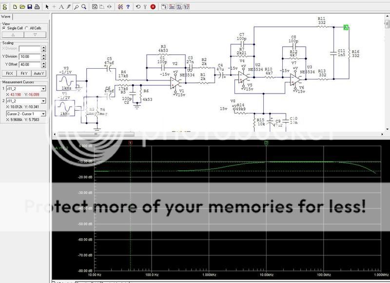
2.Yes, from +15V 😉
3.Yes, that's not the option without rearranging input stage. But hf filter and attenuation is almost the same (except +6db shelving) with AK schematics I posted before.
It's not flat, I measured , but here's the sim. Identical as measured.
2.Yes, from +15V 😉
3.Yes, that's not the option without rearranging input stage. But hf filter and attenuation is almost the same (except +6db shelving) with AK schematics I posted before.
Moby said:1.Let's clear this "flat" forever.
It's not flat, I measured , but here's the sim. Identical as measured.
Did you only measure the output stage, or with DSP?
Ow wait, this is the INPUT stage.. 
Did you also measure what is coming out when the DSP is not doing anything?
Did you also measure what is coming out when the DSP is not doing anything?
The frequency response of the stock unit is flat! Your so called 'measurement' is a simulation based on schematics but not real assembly of the input buffer PCB.
Yes, I added that 332+332+332/15n in the air...
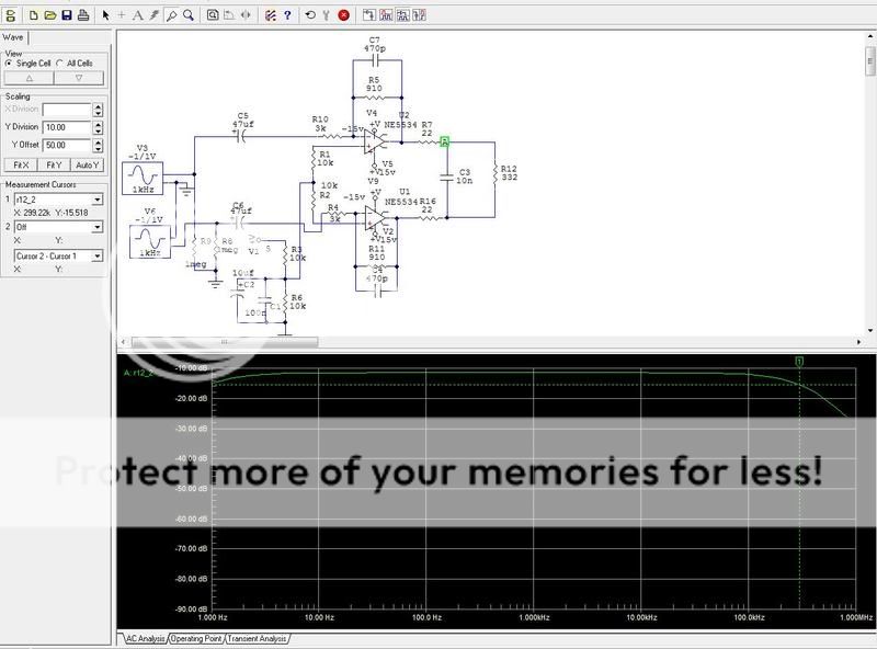
Maybe something like this can work. -16.5db attenuation, flat and with 10k of load....
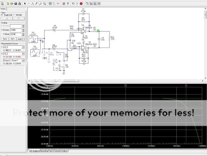
Maybe something like this can work. -16.5db attenuation, flat and with 10k of load....
I will repeat my measurements again, but Jan has same result like me. I was asking all the time where that +6db gone at the end of unit. If you skip this shelving filter (Jan version) you will again have a flat unit but "more natural". I didn't checked that but I believe Jan ;-)😉 So, highs are "burned" somewhere, nobody knows where...
How can an input buffer having a 6 dB shelve, have the same output at the end of the line as one not having this shelve 😕
4real said:How can an input buffer having a 6 dB shelve, have the same output at the end of the line as one not having this shelve 😕
That's exact what I was asking😕
4real said:Could be? Maybee the cable impedance is 333 ohms?
I don't know why they chose 330 ohms, but the reason that they used the 1/3 (-10dB about) attenuation is most probably because they had to bring pro input levels down to the input range (4.2V pk-pk) of the ADC.
Jan Didden
4real said:
Did you only measure the output stage, or with DSP?
It's very clear why it is shelving. It's C3 in conjunction with R1 and R2 in post 164.
Jan Didden
4real said:How can an input buffer having a 6 dB shelve, have the same output at the end of the line as one not having this shelve 😕
Has anyone measured a fully stock unit, analog in -> analog out, all filters out, all levels 0dB? Maybe the stock unit isn't really flat?
Jan Didden
- Home
- Source & Line
- Digital Line Level
- Behringer DCX2496 digital X-over